Chapter 4: Wiring the INTEGRITY Lightbar in the Vehicle
24
Integrity Lightbar
5.
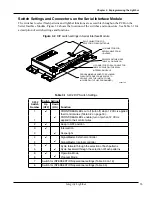
Install the three-foot-long, 24-conductor cable from the lightbar to the J1 input connector of the Serial
Interface Module.
NOTE:
Powering multiple devices with a common control wire may cause one or more devices to briefly
remain functional after signal power is removed. For example, due to the high input filter capacitance, a
strobe supply can briefly supply the current required to signal a lightbar function to remain on. If necessary,
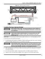
use a relay to isolate devices with large filter capacitors (Figure 4.2). All components/wires are user-supplied.
SHOCK HAZARD—Strobe and HID light systems generate high voltages. Disconnect
power from the system and wait at least 5 minutes before opening the unit. Do not
apply power to the unit while the unit is open. Failure to follow this warning could
result in serious injury or death.
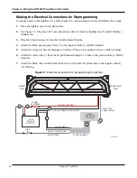
Figure 4.2 Relay for isolating devices with large filter capacitors
290A7446
+12 Vdc
CONTROL LEAD
(12 Vdc SIGNAL ACTIVATED)
RELAY
FUSE*
STROBE SUPPLY
*FUSE AMPERAGE DEPENDS ON AMPERAGE OF DEVICES
Wiring the Serial Interface Module
FUSE ELECTRICAL SOURCES—Always fuse current/voltage sources with a fuse
connected near the power source. Be sure that the fuse is properly rated to protect
the electrical load, the wiring and the connectors used in the circuit. Failure to
follow this notice could result in vehicle or equipment damage.
This section is an overview of default settings that are activated when connecting LED and Mode control
wires to 12 Vdc (+BAT). The basic light functions of the lightbar must be controlled by an installer-supplied
control head. All programming and changes to default settings should be done after quick testing the lightbar
and before installation. Programming is covered in “Programming Priority Modes 1, 2, 3, and Intersection”
on page 17.
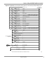
For a description of the control wires from the Serial Interface Module, see Table 3.3 on page 19. For typical
installations with common controllers and switch boxes, see the wiring schematics starting on page 21 in
Chapter 4.
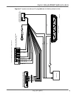
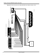
For wiring the controller functions to the 24-pin cable harness of the Serial Interface Module, see Table 3.2
on page 16 and the figures on pages 29 and 30. If additional wire is necessary for the harness (except
ground), 22 AWG wire is adequate. The ground wires must be extended with 16 AWG or thicker wire.
Priority Modes 1, 2, and 3
To activate a priority mode, apply 12 Vdc (+BAT) to a mode control wire. Mode 3 (black/red) overrides
Mode 2 (blue/white), and Mode 2 overrides Mode 1 (blue). You can program one of the flash patterns in
the lightbar to each Mode input.
Summary of Contents for Integrity44
Page 2: ...blank page ...

