13
Installation
Signaling Standalone Manual
Federal Signal
www.fedsig.com
3.
Secure the unit to a wooden mounting surface with #10 by 1-inch wood screws. If
mounting on a metal surface, drill 13/64-inch diameter holes and secure the unit with
#10 screws, lock washers, and nuts.
4.
Route wires through the 1/2-inch threaded openings into the Informer15 Speaker unit
per National and Local Electrical codes.
5.
Reposition speaker projector if necessary to obtain the desired sound coverage.
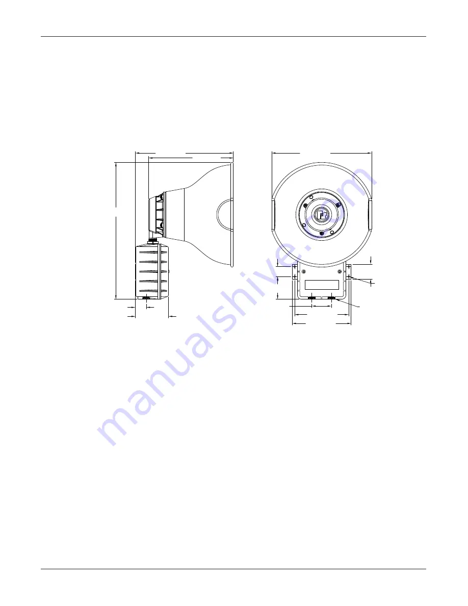
Loosen the collar nut and move the projector to the desired position. See Figure 1.
Figure 1 Depth and Height of Informer15 Speaker
1.50" [38 mm]
5.50" [140 mm]
6.00" [152 mm]
CONDUIT
ENTRANCE
1/2"-14" NPT
(2 PLCS.)
1.00" [25 mm]
2.30" [58 mm]
Ø0.20" [Ø5 mm]
MOUNTING HOLES
(4 PLCS.)
10.0" [253 mm]
3.38" [86 mm]
1.12" [28 mm]
2.00" [51 mm]
13.9" [353 mm]
10.2" [258 mm]
8.6" [219 mm]
Opening the Housing
Tools required:
Phillips head screwdriver
To open the housing, loosen the two cover screws while supporting the cover so it does
not fall. (The cover screws are retained in the housing.) Carefully remove the visual
indicator cable to allow the cover to be removed.


