background image

14


Installation

Informer15 Speaker (Model IS-I-P15X Series C) 

Federal Signal

 www.fedsig.com

Wiring the Network and Power Connections

PoE model (See Figure 2)

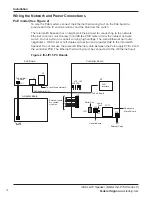
To wire the PoE models, connect the Ethernet field wiring to J1 on the PoE board to 

provide both the IP communications and the PoE from the switch. 
The Informer15 Speaker has an eight-pin Ethernet port for connecting to the network. 

Ethernet wire runs must be less than 328 feet (100 meters) from the nearest network 

switch. Do not install in a conduit carrying high voltage. The wired Ethernet port auto-

negotiates a 10/100, full or half-duplex connection and provides PoE to the Informer15 

Speaker. Do not remove the prewired Ethernet cable between the PoE supply PCB J2 and 

the controller PCB. The Ethernet field wiring must be connected to the J1 Ethernet input.

Figure 2 IS-I-IP15 PC Boards

External Inputs
dry contact 
closures

To PoE Board

JP2

Serial Port

Removable 
MicroSD card

Visual Indicator

External Relay

1
2
3
4

JP13

JP11

JP3

Lamp

Test

JP1

JP6

JP8

JP9

JP4

JP5

LAN
Interface

Controller Board

PoE Board

Amplifier Board

To Amplifier 

Board

To PoE 

Board

To Controller LAN

To Local Area Network 

JP1

J1

J2

M1

Summary of Contents for IS-I-IP15X

Page 1: ...Signaling Standalone Manual 25500843 Rev A0 0423 Printed in U S A Copyright 2023 Federal Signal Corporation Informer15 Speaker Model IS I IP15X Series C Indoor Outdoor Audible Speaker...

Page 2: ...l 1 708 534 3400 This limited warranty is in lieu of all other warranties express or implied contractual or statutory including but not limited to the warranty of merchantability warranty of fitness f...

Page 3: ...See Figure 3 15 Wiring to the Controller Board 15 Closing the Housing 17 Testing 17 Programming 18 Automatic Volume Level Control 18 Digital Inputs 18 WAV Files 18 WAV File Control Commands 18 Functi...

Page 4: ...Visual Indications for the Controller Board 11 Table 9 Visual Indications for Amplifier Board 11 Table 10 Environmental and Physical 11 Table 11 Input and Output Configuration 18 Table 12 Examples of...

Page 5: ...of the mounting location for this Informer15 Speaker its controls and the routing of the wiring is to be accomplished under the Facilities Engineer and the Safety Engineer direction Listed below are...

Page 6: ...hese instructions in a safe place and refer to them periodically Give a copy of these instructions to recruits and trainees Give a copy to anyone who is going to service or repair the Informer15 Speak...

Page 7: ...ate the Informer15 This may be useful if the location has no network connectivity but where voice and tone alerts from locally activated inputs are required The Informer15 includes one output to contr...

Page 8: ...ice or tone files Deliver intelligible voice messages from locally prerecorded files Removable microSD card for custom message generation Store up to 4000 voice or tone messages that total up to 17 ho...

Page 9: ...24 Vdc model 24 Vdc 1 0 A Serial Port Protocol FLASH programming and configuration Default 9600 bit s 8 data 1 stop no parity Configurable up to 115 200 bit s Open Collector Output Maximum 30 V or 100...

Page 10: ...re to factory defaults JP6 Open Collector Output 1 Output 1 Open Collector Output 2 Output 1 24 Vdc JP8 Option1 Jumper Short pins 1 and 2 for Standalone Option JP9 Option2 Jumper Short pins 1 and 2 fo...

Page 11: ...cations for the Controller Board D1 Power D2 Digital Input 1 active D3 Listen D4 Talk D5 Digital Input 2 active D7 Network connected D8 CPU running D9 Digital Input 3 active D11 Digital Input 4 active...

Page 12: ...or slightly downward and ensure that the front of the speaker is clear of obstructions SHOCK HAZARD Property damage serious injury or death could occur if the projector is mishandled during installati...

Page 13: ...btain the desired sound coverage Loosen the collar nut and move the projector to the desired position See Figure 1 Figure 1 Depth and Height of Informer15 Speaker 1 50 38 mm 5 50 140 mm 6 00 152 mm CO...

Page 14: ...install in a conduit carrying high voltage The wired Ethernet port auto negotiates a 10 100 full or half duplex connection and provides PoE to the Informer15 Speaker Do not remove the prewired Ethern...

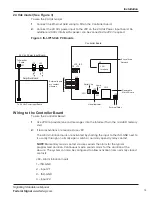
Page 15: ...oard 24 Vdc Power Input Board Amplifier Board To Amplifier Board To 24 Vdc Power Input Board JP1 JP2 JP3 M1 GND GND 24 Vdc 24 Vdc Wiring to the Controller Board To wire the Controller Board 1 Use JP13...

Page 16: ...current ratings listed in the Specifications section of this manual When using this feature the open collector relay outputs turn on until one of the following occurs The programmed default timeout o...

Page 17: ...earing protection should be worn if standing within close proximity to the device while testing Recommendations in the OSHA Sound Level Standard 29 CFR 1910F should not be exceeded To test the system...

Page 18: ...If multiple continuous inputs are active the WAV files and relay outputs associated with each input will activate in sequence Lower priority inputs are ignored while higher priority inputs are active...

Page 19: ...after is received 5000 Valid WAV file index numbers are limited to 1 4093 The entry is discarded 5 seconds after is received Function Control Commands Function Control commands are used to activate f...

Page 20: ...l network equipment such as sirens SIU or PA interface devices If the Informers are used with the Commander application you must reserve a unique numeric site ID number for use by the Commander softwa...

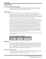
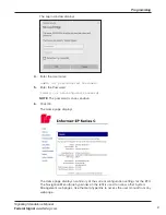
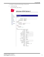
Page 21: ...Password fedsig or preconfigured Password NOTE The password is case sensitive 6 Click OK The Home page displays The Home page displays a summary of the current configuration settings for the RTU The...

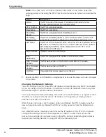
Page 22: ...DIGI Firmware Version The firmware version of the DIGI Connect ME 9210 module RTU Firmware Version The firmware version of the RTU Up Time The elapsed time since power up or reboot 7 Record the MAC a...

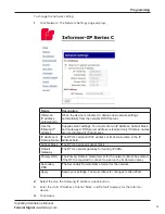
Page 23: ...are used instead of IP addresses IP Address or Domain Name The RTU s assigned IPV4 address or its domain name in the IP address field Subnet Mask The RTU s assigned subnet mask Default Gateway The RT...

Page 24: ...n use DHCP to simplify Informer deployment but MAC address discovery tools may not traverse routers and maintenance may be more difficult 2 Configuring the RTU Settings When the RTU is used with Comma...

Page 25: ...25 Programming Signaling Standalone Manual Federal Signal www fedsig com To change the configure the RTU Settings of the Informer 1 Click RTU Settings The RTU Settings page displays...

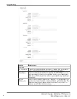
Page 26: ...48 character text field to describe the RTU This can be the physical address of the site or any other text string The description field has a 255 character limit and can be scrolled to view additiona...

Page 27: ...r leave this field blank Address Extension The RTU s assigned Address or Extension number This field is required Registration User ID Username for registration If this field is blank the Address Exten...

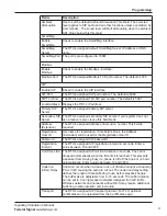
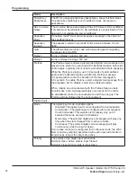
Page 28: ...of public address audio will be buffered and play out after the Pretone message It is good practice to limit the duration of Pretone messages to 3 5 seconds To enable Pretone select a digital voice me...

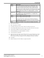
Page 29: ...2 Turns on Relay 2 when the input is active The relays will remain on while the DV messages are playing in Momentary mode The relays will remain on as long as the input is active in Continuous mode A...

Page 30: ...hen the speaker is not receiving a page playing a WAV file or a tone This feature allows phones and other VoIP devices to listen to the background audio The Informer100 will receive audio from up to 5...

Page 31: ...pages Multicast Transmit Zone siren audio All audio sources except incoming Multicast Receive Zones are routed to the Multicast TX Zone Configure only one RTU per Zone with a Multicast TX Zone to prev...

Page 32: ...figured or if two zones are configured with the same priority the RTU listens to audio only from the first source that started multicasting until the RTU detects the original source has stopped sendin...

Page 33: ...plays Field Description SIP IP Filter Start IP Address Starting IP Address in dotted decimal format End IP Address Ending IP Address in dotted decimal format The ending IP address must be a greater va...

Page 34: ...ws Full Admin privileged users to create users create passwords and assign security privileges You cannot delete the Admin user or change the security privilege for the Admin user You can change the A...

Page 35: ...ck to enable the factory support user When enabled a hidden static user and password is enabled for Federal Signal technical support You can disable this user Apply Saves your settings You must reboot...

Page 36: ...ficate validation File type Filename CA certificate ca cert pem Device SSL certificate cert pem Device private key key pem To upload a certificate file 1 Click Certificates The Certificates page displ...

Page 37: ...se File to open a dialog box Select the new image bin file to upload Upload Click the Upload button to upload the new image bin file 2 Click Browse to open a dialog box to select the new image bin fil...

Page 38: ...ion Settings Use the Reboot page to reboot the device and load new configuration settings To reboot the device and load new configuration settings 1 Click Reboot The Reboot page displays 2 Click the R...

Page 39: ...10 10 10 10 Primary Secondary DNS 0 0 0 0 0 0 0 0 Admin user name admin Admin user password fedsig User 1 User 4 username password blank Factory Support User Enabled To restore configuration to factor...

Page 40: ...factory defaults 4 Reboot the device for the changes to take effect Using the RESET Button To restore the configuration to the factory default by using the RESET button 1 Remove power from the Informe...

Page 41: ...ort JP11 on the control board for 10 seconds and then remove the short 3 Wait 60 seconds for the Informer to reboot with the factory default settings You must reenter all local configuration settings...

Page 42: ...the device is painted Periodically inspect this device to verify that there are no foreign substances in or in front of the speaker which will reduce its notification effectiveness Periodic evaluation...

Page 43: ...e Musical Tone 13 FWS 13967 TM13 5 sec Evac Amplitude Modulated Siren 479 Hz 14 FWS 13968 TM14 5 sec Air Horn Steady Horn 400 Hz and 800 Hz 15 FWS 13969 TM15 5 sec Chime Single Strike Chime Musical To...

Page 44: ...orn 15 sec 52 horn 15 sec 42 FWS 13996 52 horn 1 sec pulses 10 times 52 horn 1 sec pulses 10 times 43 FWS 13997 1 kHz_30 sec 1 kHz_30 sec 44 FWS 13998 5 sec Alt Steady 5 sec Alt Steady 45 FWS 13999 5...

Page 45: ...WS 14016 Tornado Warning Seek Shelter Attention Attention Tornado warning Seek shelter immediately Attention Attention Tornado warning Seek shelter immediately High Winds 63 FWS 14017 High Wind Attent...

Page 46: ...als Stay Inside Hazardous materials incident Stay inside close all doors and windows Remain calm and wait for further instructions 78 FWS 14032 Chemical Release Seek Shelter Warning Chemical release t...

Page 47: ...g Warning Do not attempt to enter unsound structures Check your area for damage and avoid risk 93 FWS 14047 Power Outage There is a building wide power outage Avoid using open flames or candles during...

Page 48: ...ty is now closed Tune to local media for further information Armed Forces Songs 109 FWS 14063 Army Song Army Song Band and Chorus 110 FWS 14064 Navy Song Anchors Aweigh 111 FWS 14065 Air Force The Air...

Page 49: ...Continuous Tone PFEER Toxic Gas Alarm 1 kHz signal Continuous Tone PFEER Toxic Gas Alarm 1 kHz signal 148 FWS 14102 Duck and Cover Duck and Cover 149 FWS 14103 Emergency Shutdown Emergency Shutdown 15...

Page 50: ...63Hz 174 FWS 19250 TM10 180 sec Gradual Horn Steady Horn Gradually Increasing in Volume 514Hz 175 FWS 19251 TM11 180 sec Temporal Slow Whoop NFPA Coded Slow Whoop 424Hz and 774Hz 176 FWS 19252 TM12 9...

Page 51: ...Tone 1163 397Hz 192 FWS 19268 TM28 180 sec Ringer Continuous Ringing Tone 560Hz and 326Hz 193 FWS 19269 TM29 180 sec Buzzer Buzzer Tone 1318Hz and 760Hz 194 FWS 19270 TM30 180 sec Attention Extremely...

Page 52: ...2645 Federal Signal Drive University Park Illinois 60484 www fedsig com Customer Support 1 800 344 4634 1 708 534 4756 Technical Support 1 800 755 7621 1 708 587 3587...

Reviews: