SECTION 8
8-14
TROUBLESHOOTING-TELESCOPIC SYSTEM
PACKING REFUSE
OPERATOR ACTION
None-MCV (Main Control Valve) shifts automatically.
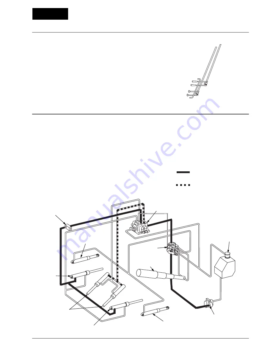
HYDRAULIC SEQUENCE
Fluid flows from the MCV (Main Control Valve) to the
case end of the carrier panel cylinders. The cylinders
extend, moving the carrier and packer panels up, pack-
ing refuse against the pushout panel. When the pres-
sure reaches 2150 PSI (148 BAR), the MCV (Main
Control Valve) shifts into neutral and the packing cycle
is completed. As the carrier cylinders apply force to
compact refuse, the pressure of the trapped fluid in the
packer cylinders will increase. Should this pressure
reach 3800 PSI (262 BAR), a relief valve will open re-
ducing the pressure by allowing some trapped fluid to
escape and return to the hydraulic tank.
PRESSURE
○ ○ ○ ○
MAIN CONTROL
VALVE
HYDRAULIC
FLUID TANK
PUMP
FRONT
CONTROL VALVE
TELESCOPIC
CYLINDER
TAILGATE LIFT
CYLINDER
CARRIER
CYLINDER
PACKER
CYLINDER
CARRIER
CYLINDER
TAILGATE LIFT
CYLINDER
P.O. CHECK
VALVE
○
○
○○○○
○
○
○ ○
○
○
○
○○ ○
○ ○
○ ○
○ ○
○ ○
○ ○
○ ○
○ ○
○ ○
○○○○○
○○○○○○○○○
○
○
○
○
○○○○○
○○○○
○
○
○
○
○
RETURN
TRAPPED FLUID
○○
○
○
○
○
○
○
○○○
○ ○
○ ○
○ ○
○
○
○
○
○
○
○
○
○
○
○
○
○
○
○○
○
○○○○○○○○○○
○○○○
○ ○
○ ○
○ ○
○ ○
○ ○
○ ○
○ ○
○ ○
○ ○
○ ○
○ ○○
Summary of Contents for LEACH 2R-III
Page 2: ......
Page 8: ......
Page 26: ...SECTION 2 2 8 ...
Page 28: ...OPERATION SECTION 3 LOCATION OF OPERATING CONTROLS 3 2 4 6 5 7 8 1 2 3 8 9 10 11 12 7 ...
Page 46: ...SECTION 3 3 20 ...
Page 54: ...SECTION 4 4 8 ...
Page 60: ...SECTION 6 6 4 PREVENTIVE MAINTENANCE 1 2 3 4 5 6 7 8 ...
Page 62: ...SECTION 6 6 6 ...
Page 76: ...SECTION 7 7 10 ...


