background image

EXPMOD-2 Pathfinder

® 

Expansion Module


Federal Signal 

www.fedsig.com

Mounting the Pathfinder Expansion Module

16   

Mounting the Pathfinder Expansion Module

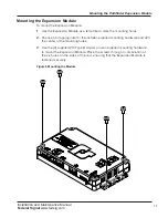
After wiring and connecting the system, the next step is to permanently mount the 

siren in the vehicle. Verify that the mounting locations you selected earlier are safe 

for installing these components. Review the following precautions before mounting 

the equipment.

AIRBAG DEPLOYMENT: Do not install equipment or route wiring in the 

deployment path of an airbag. Failure to observe this warning will reduce the 

effectiveness of the airbag or potentially dislodge the equipment, causing 

serious injury or death.

SEAT REMOVAL PRECAUTION: If a vehicle seat is temporarily removed, verify 

with the vehicle manufacturer if the seat needs to be recalibrated for proper 

airbag deployment.

UNIT REQUIRES AIR FLOW: Do not install the siren in areas where the air flow 

is restricted. Do not mount the unit near a heater duct or under the hood.

MODULE IS NOT WATERPROOF: The housing of the siren is NOT waterproof.

Select a mounting location that allows the vehicle, controls, and microphone to 

be operated safely under all driving conditions. To identify safe mounting areas 

for equipment inside the vehicle, consult the vehicle manufacturer’s guidelines. 

To avoid driver distraction and unreliable switch activation, the mounting location 

must not allow any movement of the unit. Installer-supplied mounting hardware is 

required to mount the siren.

Summary of Contents for Pathfinder Siren Series

Page 1: ...annel Expansion Module Taillight Flasher Pathfinder Siren Series Installation and Maintenance Manual 25500587B B0 0919 Printed in U S A Copyright 2019 Federal Signal Corporation Pathfinder Expansion M...

Page 2: ...deral Signal Drive University Park IL 60484 email to info fedsig com or call 1 708 534 3400 This limited warranty is in lieu of all other warranties express or implied contractual or statutory includi...

Page 3: ...g the Expansion Module on a Vehicle 11 Overview of the Pathfinder Connections 11 Convergence Network Ports 11 Expansion Module Relay Outputs 12 System Power 12 Mounting the Pathfinder Expansion Module...

Page 4: ...4 Figures Figure 1 DIP Switch 9 Figure 2 Relays 12 Figure 3 Convergence Network Serial Ports 12 Figure 4 Bottom View 13 Figure 5 Circuit 15 Figure 6 Mounting the Module 17 Figure 7 Pathfinder Expansio...

Page 5: ...g with proficiency in the installation and service of safety warning equipment Always refer to the vehicle s service manuals when performing equipment installations on a vehicle Sound Hazards Your hea...

Page 6: ...icle s occupants Refer to the National Institute of Justice guide 500 00 for further information Mounting the speakers behind the grille will reduce the sound output and warning effectiveness of the s...

Page 7: ...ff and all operating personnel File these instructions in a safe place and refer to them when maintaining or reinstalling the product Failure to follow all safety precautions and instructions may resu...

Page 8: ...y angled glass reduce the light output of the warning light This may reduce the effectiveness of the light as a warning signal If your vehicle has dirty tinted or steeply angled glass use extra cautio...

Page 9: ...ed as a hub to any FS Convergence Network Federal Signal product A DIP Switch on the product allows for a second expansion module in the system if necessary Normally the expansion module powers up whe...

Page 10: ...parts included with the Expansion Module kit After unpacking the kit examine it for damage that may have occurred in transit If the product has been damaged file a claim immediately with the carrier s...

Page 11: ...ions for the siren amplifier and Expansion module Read and understand all instructions included with related equipment before installing it Ensure that all wiring is protected from damage during norma...

Page 12: ...ers All of the relays 1 18 have a software programmable current limit By default the current limit setting is disabled See the Pathfinder Configuration Software for all available programming options a...

Page 13: ...BCM 2 Relay 12 Feed to Driver Side Tail Light Panel Relay 12 J10 5 White Input BCM Disconnect 3 Feed from BCM to Passenger Side Turn Light J10 10 Brown Output Relay 16 BCM 3 Relay 16 Feed to Passenger...

Page 14: ...ay Output 2 J9 1 Gray Relay 3 Flashing Relay Output 3 J9 7 Black Relay 4 Flashing Relay Output 4 J9 8 Table 5 J12 Flashing Outputs and 20 Ampere Outputs Wire Color Blackout Relay Output Flashing Outpu...

Page 15: ...to the light The flashing output is connected to the output to the light through a diode During normal operation the tail brake reverse light turns on when either the Body Control Module applies a si...

Page 16: ...ious injury or death SEAT REMOVAL PRECAUTION If a vehicle seat is temporarily removed verify with the vehicle manufacturer if the seat needs to be recalibrated for proper airbag deployment UNIT REQUIR...

Page 17: ...to mark the mounting holes 2 Choose a bit appropriate for the installer supplied mounting hardware and drill the center of the mounting holes 3 Use the 4 supplied 10 Type B screws or user supplied mou...

Page 18: ...Programming the Pathfinder Expansion Module The Expansion Module can be programmed through the Pathfinder Configuration program Download the software at https www fedsig com software downloads The sc...

Page 19: ...phased between different channels The intensity of each light can be set and you can specify whether the Expansion Module is a Primary or Secondary Module as shown below BCM disconnect allows the use...

Page 20: ...or the nature of the malfunction Address all communications and shipments to the following Federal Signal Corporation Service Department 2645 Federal Signal Drive University Park IL 60484 3167 Orderin...

Reviews: