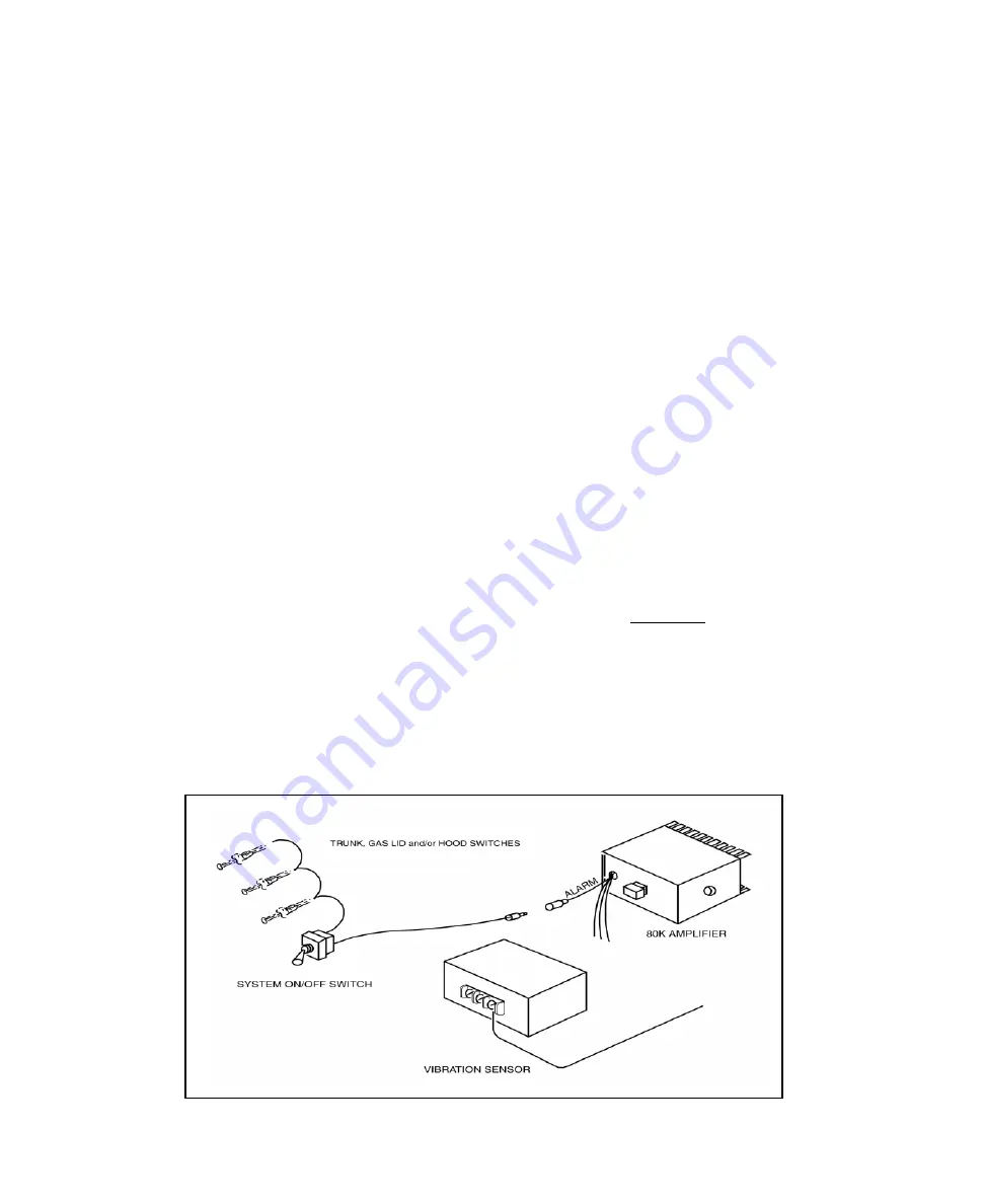
SECTION VIII - INTRUSION ALARM
For All Models
PURPOSE & OPERATION
1. The
80K
amplifier is capable of producing a 1600 Hz.
steady tone. The tone can be used to warn out-of-vehicle
driver that the vehicle or its contents are endangered.
2. The tone occurs when ground (-) is applied to the amplifier’s
“ALARM”
wire. Ground can be supplied by a motion-detector
device or by individual switches at the trunk, gas lid, and/or
hood.
3. A separate on/off switch may be used to permit normal use of
the vehicle. The switch may be a keyed type or a concealed toggle
having single-pull; single-throw contacts.
Both types are available from radio parts stores. Connections
are as follows:
a) Using 18ga. wire, connect one switch terminal
(either one) to
“ALARM”
wire.
b) Connect remaining terminal as outlined below.
MOTION DETECTOR
1. Depending on manufacturer, a motion detector will have an
output terminal or wire that becomes ground (-) or positive (+)
when the detector senses vehicle movement. This output may be
used as follows:
a) Ground (-) Output:
Using 18ga. wire, connect output to remaining
terminal of system on/off switch.
b) Positive (+) Output:
Install a light duty (1 to 3A) - SPST relay. Use
output to operate relay. Using 18 ga. wire, connect
relay contacts so they apply ground to
“ALARM”
wire.
Note
: If a relay is undesirable, the positive output may
be used to operate siren sounds or the air horn:
Page 9
c) Connect one terminal (either one) of system on/off
switch to desired pin in amplifier 12-pin connector
(see faceplate for functions) or to “AIR HORN” wire
in 3-pin amplifier power connector.
2. Connect remaining terminals of motion detector
according to manufacturer’s instructions.
INDIVIDUAL SWITCHES
1. Spring-loaded switches, like those used in cars for
turning on interior lights are internally grounded and
have SPST contacts. They also have one insulated
terminal. Other switch styles, such as mercury tilt
switches, can also be used.
2. Connect switches as follows:
Using 18ga wire, connect insulated terminal of all
switches together. Connect one wire from joined
switches to remaining terminal of system on/off
switch.
3. If switches have two terminals, connect one
(either one) to vehicle chassis. If internally
grounded switches are being installed on a plastic
or insulated surface, run an 18ga. wire from vehicle
chassis to the switch body.
WARNING
If installed on the vehicle’s exterior, the system
on/off switch should be a water-resistant type or
installed in a water-free area to prevent contact
corrosion. Corrosion will eventually form a bridge
across contacts that will freeze the switch in “on”
condition thereby making the Intrusion Alarm active
during normal vehicle use.
d) Connect remaining terminal of system
on/off switch to positive output of motion
detector.


