
- 23 -
MAINTENANCE
Shelf Light Bulb Replacement
1.
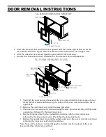
Remove both rear doors as described in the “Door Removal” section of this manual.
2.
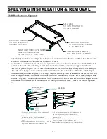
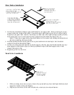
Remove shelving from unit through rear door opening as described in the “Shelving Installation and
Removal” section of this manual.
3.
Unplug appropriate light housing cord from socket and remove light fixture from unit through rear door
opening.
4.
Remove the plastic lens. Starting at one end of the light, push in on the topside of plastic lens until the
plastic lens clears the light fixture housing and peel the lens away from the fixture housing edge.
5.
The shelf light fixture uses a spring-loaded socket at one end. To remove the bulb push the bulb
towards the spring-loaded socket until the opposite ends drops out of the socket.
6. Reinstall new bulb in the same manner as described in the Bulb Removal Procedure. Be sure bulb is
secure in bulb receptacles.
Note: Be sure to use a direct equivalent to the original bulb.
Top Light Bulb Replacement (All Service cases and Dry Self Serve Cases)
1.
Remove both rear doors as described in the “Door Removal” section of this manual.
2.
Remove shelving from unit through rear door opening as described in the “Shelving Installation and
Removal” section of this manual.
3.
Remove the (3) top light lens retaining screws along the top frame.
4.
Peel the light housing out from top frame across the entire length of light lens.
5.
To remove bulb from top light housing, grip the bulb receptacle end caps at each end of bulb. Pull
the bulb receptacle end caps straight down. Once bulb and bulb receptacle end caps are removed
from top light housing remove the bulb receptacle end caps from end of bulb.
6.
Reinstall new bulb in the same manner as described in the Bulb Removal Procedure. Be sure bulb is
secure in bulb receptacles. Note: Be sure to use a direct equivalent to the original bulb.
7.
Reinstall top light lens and lens retaining screws
Top Light Bulb Replacement (Refrigerated Self Serve Cases)
1.
Remove outer and inner rear doors as described in the “Door Removal” section of this manual.
2.
Remove shelving from unit through rear door opening as described in the “Shelving Installation and
Removal” section of this manual.
3.
Remove the plastic lens. Starting at one end of the light, push in on the topside of plastic lens until
the plastic lens clears the light fixture housing and peel the lens away from the fixture housing edge.
4.
The top light fixture uses a spring-loaded socket at one end. To remove the bulb push the bulb
towards the spring-loaded socket until the opposite ends drops out of the socket.
5.
Reinstall new bulb in the same manner as described in the Bulb Removal Procedure. Be sure bulb
is secure in bulb receptacles