

- 33 -
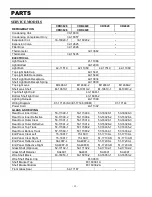
SELF-SERVE MODELS
CRB3628SS
CRB4828SS
CD3628SS
CD4828SS
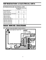
REFRIGERATION
CRR3628SS
CRR4828SS
Condensing Unit
30-17318
-
Condensing Compressor Only
30-18058
Evaporator Coil
33-17315-1
33-17315-2
-
Expansion Valve
32-17407
-
Filter Drier
32-12626
-
Thermometer
32-13662
Thermostat
32-15495
-
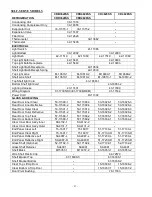
ELECTRICAL
Light Switch
41-11066
Light Ballast
39-12902
39-12903
Light Bulb
42-11519
42-11069
42-11519
42-11069
Top Light Bulb Cap
42-15441
42-10834
Top Light Bulb Receptacle
42-15440
42-10833
Shelf Light Bulb Receptacle
42-10834
Shelf Light Bulb Recept.Spring
42-10833
Top Light Lens
M-10610-1
M-10610-2
M14669-1
M14669-2
Shelf Lens Shelf
M-10610-1
M-10610-2
M-10610-1
M-10610-2
Top Shelf light Cord
43-16861-1
Bottom Shelf light Cord
-
43-16861-2
Lighting Harness
43-17401
43-17099
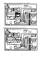
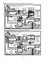
Wiring Diagram
91-17395(SC)/91-17396(REM)
91-17144
Power Cord
43-11302
GLASS & SHELVING
Rear Door Inner Clear
53-17390-1
53-17390-3
53-16026-1
53-16026-3
Rear Door Inner Reflective
53-17390-2
53-17390-4
53-16026-2
53-16026-4
Rear Door Outer Clear
53-17391-1
53-17391-3
53-16028-1
53-16028-3
Rear Door Outer Reflective
53-17391-2
53-17391-4
53-16028-2
53-16028-4
Rear Door Top Track
57-17388-1
57-17388-2
57-16035-1
57-16035-2
Rear Door Bottom Track
57-17389-1
57-17389-2
57-16034-1
57-16034-2
Clear Inner Door Ass'y Inner
SA4132-1
SA4132-2
-
Clear Inner Door Ass'y Outer
SA4131-1
SA4131-2
-
End Panel Clear Left
15-16017
15-16017
51-17130-L
51-17130-L
End Panel Clear Right
15-16017
15-16017
51-17130-R
51-17130-R
End Panel Reflective Left
SA4087-L
SA4087-L
51-17230-L
51-17230-L
End Panel Reflective Right
SA4087-R
SA4087-R
51-17230-R
51-17230-R
Glass Shelf (Optional)
52-17102-3
52-17102-4
52-17102-1
52-17102-2
Glass Shelf Retainer
SA4091
SA4091
SA4091
SA4091
Shelf Black
M15357-1
M15357-2
63-16053-1
63-16053-2
Wire Shelf Plastic Clip
-
64-72570
Shelf Bracket Top
67-16038-3
67-16038-1
Shelf Bracket Bottom
-
67-16038-2
Clear Top Lift Up Door
-
15-16036-1
15-16036-2
Clear Bottom Lift Up Door
-
15-16037-1
15-16037-2
Door Pivot Bushing
-
78-17333


