- 9 -
OPERATING INSTRUCTIONS
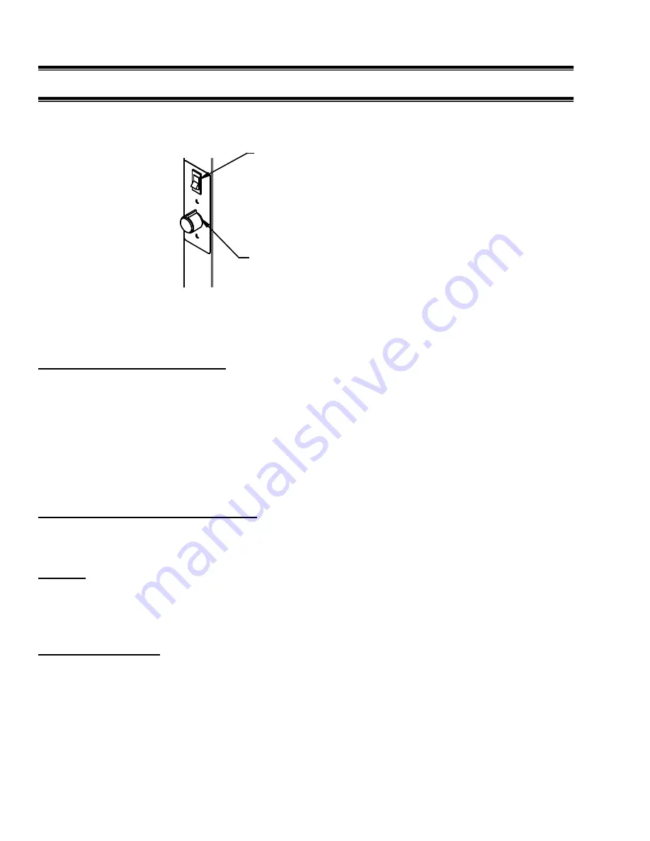
Controls (Refrigerated Units)
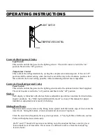
Light Switch
This switch controls the power to the lighting circuit. The switch rocker is red in the “on”
position, black in the “off” position.
Temperature Control
This controls the refrigerated side by cycling the compressor/condensing unit. It has an “off”
position and the coldest setting when the knob is set all the way in the clockwise position. Set
this control at the lowest setting possible, while maintaining desired case temperature.
Controls (Non-Refrigerated Units)
Power Switch
This switch controls the power to the lighting circuit and to the optional interior fan if supplied.
The switch rocker is red in the “on” position and black in the “off” position.
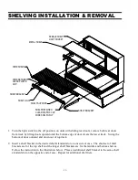
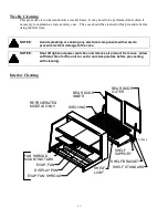
Shelves
Each display is furnished with shelves that are adjustable up and down and can be tilted in three
angular positions. See “Shelving Installation & Removal” section of this manual for proper
installation, adjustment and removal of shelving.
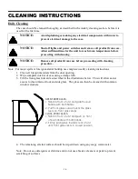
Sliding Rear Doors
The doors can be easily removed by lifting doors upward until the bottom edge of door clears the
lower track. Swing the bottom of door outward and down out of top track.
Clean the door track frequently for easy door operation. A Very light film of lubricant, such as
PAM, will help the doors slide easily.
On 59” and 77” models: If rear doors are falling out of track adjust the base center leg lever
located under rear of base taller. If rear doors are difficult to remove from track adjust leg
leveler shorter.
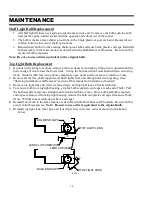
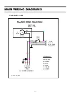
LIGHT SWITCH
TEMPERATURE CONTROL
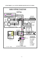
E1954-8
Summary of Contents for ECGR50
Page 29: ...29...