background image

 
Shelves


The RSSM has 15” solid metal shelves as standard. These shelves are installed at the 


factory. 


The shelves are adjustable in 1-

5/8” increments. To adjust the shelves, first remove the  shelf 


from the shelf brackets. Remove the shelf bracket from the shelf standard and reposition as 


desired. If optional shelf lights are installed, it will be necessary to unplug   the shelf light 


cord before repositioning the shelf brackets.  


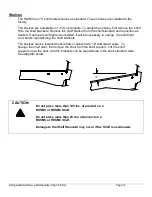
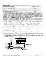
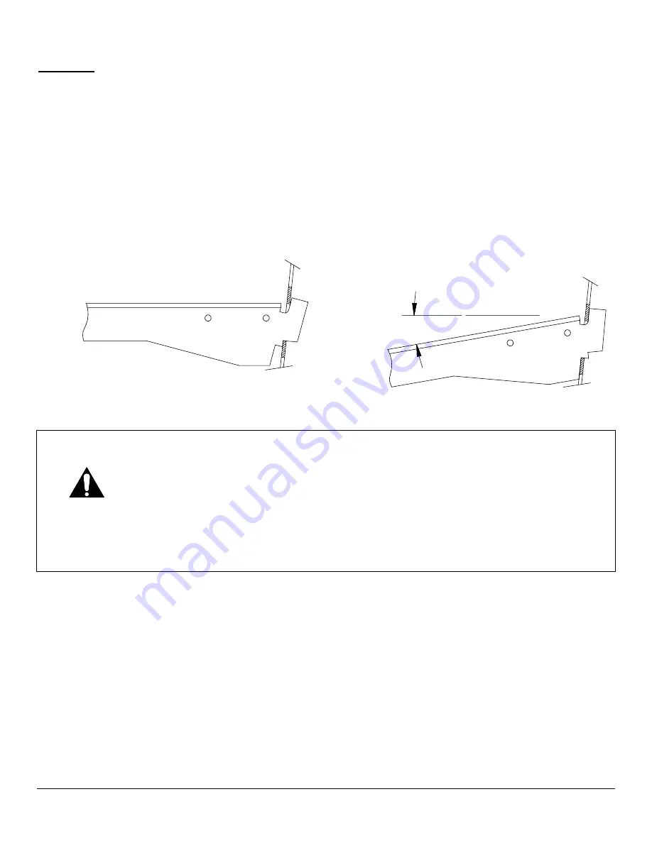
The shelves can be installed horizontally or slanted at a 10º downward angle.  To 


change the shelf slant, first remove the shelf from the shelf support.  Lift the shelf 


supports up at the back until the brackets can be repositioned in the shelf standard slots.   


See diagram below 


10 °


  CAUTION: 


Do not place more than 100 lbs. of product on a    


RSSM3 or RSSM4 Shelf. 


Do not place more than 80 lbs. of product on a  


RSSM5 or RSSM6 Shelf. 


Damage to the Shelf Standard may occur if the Shelf is overloaded.


Refrigerated Self-Serve Merchandiser (High Profile) 


Page 13 

Summary of Contents for RSSM360

Page 1: ...78 RSSM678 RSSD678 Self Contained Remote Models Includes Drop In NSSM INSTALLATION OPERATION INSTRUCTIONS KEEP THIS MANUAL FOR FUTURE REFERENCE Engineering and technical data are subject to change wit...

Page 2: ...rounding Requirements 6 Permanent Connection 6 Cord Connection 7 OPERATING INSTRUCTIONS 8 Initial Start Up 8 Light Switch Lights 8 Light Replacement 8 Digital Display 8 Placing Product In Case 8 Energ...

Page 3: ...lity 30 REFRIGERATION ELECTRICAL DATA 31 RSSM360 RSSM378 RSSD360 RSSD378 31 31A RSSM460 RSSM478 RSSD460 RSSD478 32 32A RSSM560 RSSM578 RSSD560 RSSD578 33 33A RSSM660 RSSM678 RSSD660 RSSD678 34 34A RSS...

Page 4: ...rical work DANGER Improper or faulty hookup of electrical components in the case can result in severe injury or death All electrical wiring hookups must be done in accordance with all applicable local...

Page 5: ...evere injury or death can occur if you ignore the message CAUTION Minor injury or damage to your case can occur if you ignore the message NOTICE This is important installation operation or service inf...

Page 6: ...r disturbances and avoid high humidity locations such as near cases with water misting or fogging devices The condenser air inlet is located in the front center of the base Do not block this inlet and...

Page 7: ...r the case frame as needed to level the case or if case is equipped with leg levelers adjust them up or down to level the case It is recommended that the leveled case be sealed to the floor with an NS...

Page 8: ...h is located on the left of the top light housing Optional Shelf Lights If optional shelf lights are furnished make certain that the shelf light cords are completely inserted into the sockets in the b...

Page 9: ...pliances on the same circuit from overloading the circuit and causing malfunction The electrical service must be grounded upon installation See the electrical data plate located at the rear of the cas...

Page 10: ...erchandiser for the proper power requirements for each merchandiser The cord is factory installed protruding from the rear of the merchandiser A separate circuit for each display merchandiser is requi...

Page 11: ...switch Led Light Replacement The light is attached to the shelf with plastic spring clips To remove a light un plug cord from end of bulb and pull down When replacing lights use direct equivalents to...

Page 12: ...rom the warmest setting at 1 and the coldest setting at COLD Cooling light This light will be on when control requires refrigeration to be on The compressor condensing unit should be running to cool t...

Page 13: ...n refrigeration control power on press and hold for approx three seconds The display will read On while the button is depressed When the control powers on the display will read the current set point a...

Page 14: ...is initiated when the defrost mode indicator illuminates on the display The control display will then return to reading the case temperature When the defrost mode indicator turns off the defrost is co...

Page 15: ...ce and is factory set The pressure control works on a differential The low pressure side is a safety to protect the compressor in the case of refrigerant loss The high pressure side is a safety to pro...

Page 16: ...before repositioning the shelf brackets The shelves can be installed horizontally or slanted at a 10 downward angle To change the shelf slant first remove the shelf from the shelf support Lift the she...

Page 17: ...ove or relocate this sensor The coil sensor is strapped to the evaporator coil and is labeled DEFROST This sensor location is critical for proper operation of the unit Do not move or relocate this sen...

Page 18: ...ration cycle Control Factory Settings The control parameters are set at the factory and cannot be manually changed in the field Control parameter changes can only be made by downloading a new set of p...

Page 19: ...r is programmed to have the condensing unit run a maximum of 60 minutes If the unit has not reached cut out temperature setting in 60 minutes the unit goes into on off cycle This typically comes into...

Page 20: ...Note Check your State and Local regulations for approved refrigerants for your install location Federal Industries is not liable for any alternate refrigerants used The control is located on the base...

Page 21: ...100 feet 2 Refrigeration parts between condensing unit and case are typically supplied by installing contractor 3 Route properly sized and designed refrigeration lines from the condensing unit to the...

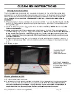
Page 22: ...ilable through any restaurant supply chain distributor NOTE Failure to coat the filter with a fresh coat of filter adhesive after cleaning will cause ineffective filter operation This will lead to plu...

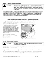
Page 23: ...dure is for Self Contained models The remote condenser coil must also be cleaned at same intervals MAINTENANCE AND DISASSEMBLY OF CONDENSATE PUMP Acrylic Air Deflector Cleaning NOTICE Clear acrylic ai...

Page 24: ...terial Clean as described in Acrylic Air Deflector Cleaning section of this manual Note For major spills or foreign material buildup use complete weekly cleaning instructions Note Detergents are not r...

Page 25: ...y Clean all shelves and shelf brackets and dry with soft dry towel 3 Lift the display decks up and out of evaporator tub 4 Clean the display deck s using warm soapy water and a brush Rinse thoroughly...

Page 26: ...NEMA 6 20P R449a 1 2HP R449a 5400 7500 NEMA 6 20P R449a 20 AMPS 3 4HP R449a 20 AMPS BACKVIEW FRO NT VIEW PLANVIEW J R R SIDEVIEW J NOTE THIS UNIT IS SUPPLIED WITH 1 REAR CONDENSER AIR INTAKE DISCHARGE...

Page 27: ...X 45 20 AMPS 15 AMPS RSSM560 62 00 X 32 50 X 60 25 59 50 X 29 50 8 850 LBS 2 TIER 10 X 57 30 AMPS 15 AMPS RSSM660 74 00 X 32 50 X 60 25 71 50 X 29 50 14 950 LBS 2 TIER 10 X 68 30 AMPS 15 AMPS NOTE ALL...

Page 28: ...e side flanges on the case These weld nuts accept the eye bolts supplied with the case for lifting the case to drop in thru the cutout made in the counter top Once the case is positioned the eye bolts...

Page 29: ...of cutout Counter rear cutout the vent opening in the back of the counter must have A minimum of 140 sq of opening similar to what is shown in the rear view picture with removable vented panel to Encl...

Page 30: ...diagram above This is needed to prevent warm condenser air from recirculating thru the condenser coil If this is not done it will affect case temperature performance shorten the life of the compressor...

Page 31: ...the Tech Support Warranty Option Email Service federalind com For Warranty Compressors please contact the Parts Department Phone 800 356 4206 and choose the Warranty Parts Option Email Parts Federalin...

Page 32: ...ormance Make sure that warm product is not being installed inside the case All product must be pre chilled prior to loading for proper case performance Check temperature pressure control for proper se...

Page 33: ...the case Any case malfunction or housekeeping problem that creates a slip fall hazard around or under a case should be corrected immediately SALE DISPOSAL Owner Responsibility If you sell or give awa...

Page 34: ...e and Minimum Circuit Ampacity REFRIGERATION Self Contained Models After 01 01 2020 Refrigeration R449a Charge Self Contained 3 Pounds The self contained models are shipped from the factory with a com...

Page 35: ...Ampacity REFRIGERATION Self Contained Models Before 01 01 2020 Refrigeration R404A Charge Self Contained 3 Pounds The self contained models are shipped from the factory with a completely operational R...

Page 36: ...Fuse Size and Minimum Circuit Ampacity REFRIGERATION Self Contained Models Refrigeration R449a Charge Self Contained 4 Pounds The self contained models are shipped from the factory with a completely...

Page 37: ...m Circuit Ampacity REFRIGERATION Self Contained Models Refrigeration R404A Charge Self Contained 4 Pounds The self contained models are shipped from the factory with a completely operational R404A ref...

Page 38: ...e Size and Minimum Circuit Ampacity REFRIGERATION Self Contained Models AFTER 01 01 2020 Refrigeration R449a Charge Self Contained 4 Pounds The self contained models are shipped from the factory with...

Page 39: ...rcuit Ampacity REFRIGERATION Self Contained Models BEFORE 01 01 2020 Refrigeration R404A Charge Self Contained 4 Pounds The self contained models are shipped from the factory with a completely operati...

Page 40: ...ize and Minimum Circuit Ampacity REFRIGERATION Self Contained Models AFTER 01 01 2020 Refrigeration R449a Charge Self Contained 4 25 Pounds The self contained models are shipped from the factory with...

Page 41: ...uit Ampacity REFRIGERATION Self Contained Models BEFORE 01 01 2020 Refrigeration R404A Charge Self Contained 4 25 Pounds The self contained models are shipped from the factory with a completely operat...

Page 42: ...208 240 Lights includes optional N A N A 2 0 208 240 Shelf lights Condensate Pan Heater N A N A Condensate Pump N A N A 0 5 208 240 Refer to the rating plate data attached to the rear of the case for...

Page 43: ...ION Self Contained Models BEFORE 01 01 2020 Refrigeration R404A Charge Self Contained 2 5 POUNDS EACH The self contained models are shipped from the factory with a completely operational R404A refrige...

Page 44: ...0871 25C35 Led Strip Light 3500K 24V Vertical Lights 42 20871 42C35 42 20871 42C35 Power supply 24V 60W 39 20986 39 20986 Field Installed Condensate Pan 47 19541 47 19541 Base Fan Assembly Remote W Co...

Page 45: ...ght Switch On Off 41 11066 41 11066 Heater Wire Assembly 43 14892 43 14892 Led Strip Light 3500K 24V Top Shelf lights 42 20871 25C35 42 20871 25C35 Led Strip Light 3500K 24V Vertical Lights 42 20871 4...

Page 46: ...35 42 20871 42C35 Power supply 24V 60W 39 20986 39 20986 Miscellaneous Components Condenser Filter 16 13647 2 16 13647 2 Front Base Grille Center SA5964 3 SA5964 3 Rear Base Grille Center Drop In Rear...

Page 47: ...escent 42 15503 42 15503 Heater Wire Assembly 43 14891 43 14891 Led Strip Light 3500K 24V Top Shelf lights 42 20871 38C35 42 20871 38C35 Led Strip Light 3500K 24V Vertical Lights 42 20871 42C35 42 208...

Page 48: ...20871 42C35 Power supply 24V 60W 39 20986 39 20986 Miscellaneous Components Condenser Filter 16 13647 2 16 13647 2 Front Base Grille Center SA5964 3 SA5964 3 Rear Base Grille Center Drop In Rear Inta...

Page 49: ...ield Fluorescent 42 15640 42 15640 Heater Wire Assembly 43 18043 43 18043 Light Switch On Off 41 11066 41 11066 Led Strip Light 3500K 24V Top Shelf lights 42 20871 48C35 42 20871 48C35 Led Strip Light...

Page 50: ...Vertical Lights 42 20871 42C35 42 20871 42C35 Power supply 24V 60W 39 20986 39 20986 Miscellaneous Components Condenser Filter 16 13647 2 16 13647 2 Front Base Grille Center SA5964 3 SA5964 3 Rear Ba...

Page 51: ...2 15441 Lamp Shield Fluorescent 42 15638 42 15638 Heater Wire Assembly 43 14893 43 14893 Led Strip Light 3500K 24V Shelf Lights 42 20871 25C35 42 20871 25C35 Led Strip Light 3500K 24V Top Light 42 208...

Page 52: ...Strip Light 3500K 24V Vertical Lights 42 20871 42C35 42 20871 42C35 Power supply 24V 60W 39 20986 39 20986 Miscellaneous Components Price Tag Molding Black W11329 22 W11329 22 Price Tag Molding White...

Page 53: ...125 Cap Tombstone Socket Fluorescent 42 15441 42 15441 Lamp Shield Fluorescent 42 15503 42 15503 Heater Wire Assembly 43 14891 43 14891 Led Strip Light 3500K 24V Top Shelf lights 42 20871 38C35 42 208...

Page 54: ...34 15 34 15 34 15 34 11 20 7 60 7 82 8 98 7 67 7 67 7 67 7 67 32 25 49 72 L 35 19 35 19 77 76 60 30 26 23 46 29 7 00 36 DEEPRSSM RSSM SLIM PROFILE 30 DEEP CUBIC FT PER SHELF CUBIC FT DISPLAY DECK TOT...

Page 55: ...NOT CYCLE WITH COMPRESSOR R G BLK BLK 1 8G A 1 4G A 1 4G A 1 4G A R BL OR W G FLOAT SW ITCH M G BLK BR OR BLK CONDENSATE PUMP OPTIONAL CONDENSATE PUMP OR CONDENSATE EVAPORATOR AS PER ORDER 1 4G A 1 8...

Page 56: ...V 1 5A CIRCUIT REQ UIRED BLK BASEFAN INSTALLEDW HENOPTIONAL CO NDENSATEPAN ISUSED STANDARDONALL REMO TES BLK R EEV 5 4 3 2 1 SUCTION SENSOR PRESS TRANS Blk Blk Red W ht Yel G rn Org Red RSV Blue Empty...

Page 57: ...k Red W ht Yel G rn Org Red RSV Blue Empty A B Sh G rn Blk TEM P3 Red TEM P2 TEM P1 RIBBON CABLE BLK LIG HTINGCIRCUIT R B R B PLUG SO CKET PLUG SHELFLIG HT LED SHELFLIG HT LED SHELFLIG HT LED SHELFLIG...

Page 58: ...ODE BLK BLACK Y G YELLOW GREEN STRIPE BLK BL BLACK BLUE STRIPE SWITCH LIGHT TO PLIG HT AND OPTIONAL VERTICLE LEDLIG HTS LIG HTINGCIRCUIT BLK W R B PO W ER SUPPLY 24V O UTPUT B R R B PLUG SOCKET PLUG T...

Page 59: ...BL BLUE Y YELLOW COLOR CODE BLK BLACK Y G YELLOW GREEN STRIPE RED WHITE ANTI SWEAT HEATER W BLK W 1 4G A TEMP PROBE PBI DEFROST PROBE PB2 14G A 18G A 18G A BLK OR RED W W R BLK Y BLK CAREL CONTROLLER...

Page 60: ...TINGCIRCUIT R B R B PLUG SOCKET PLUG R B R B PLUG SO CKET PLUG SHELF LIG HT LED SHELF LIG HT LED SHELF LIG HT LED SHELF LIG HT LED SHELF LIG HT LED TO PLIG HT LED SH ELFLIG HT LED SH ELFLIG HT LED SH...

Page 61: ...SE NEMA L14 20R GROUND BLK BLK POWER CORD WITH NEMA L14 20R PLUG G OPTIONAL POWER CORD W R G RECEPTACLE PO W ERIN W R BLK G CO NDENSER FAN CO M PRESSO R RELAY 4 5 2 1 FAN MOTOR LEAD REMOVED FROM TERMI...

Page 62: ...4GA TEMP PROBE PBI DEFROST PROBE PB2 1 4G A 1 8G A 1 8G A BLK BLK W W BLK W Y BLK ELECTRONIC CONTROLLER 1 1 1 0 9 8 7 6 5 4 3 2 1 FAN FAN M PLUG PLUG M PLUG BLK BLK RIBBED W BLK 1 4GA 1 4GA RED WHITE...

Page 63: ...R Y Y Y Y B BO X BLK 1 4G A CO M PRESSO R B COMPRESSOR RELAY CO M PRE SSO R A COMPRESSOR RELAY CONDENSER FAN 4 5 1 2 4 5 1 2 BLK 1 4G A 1 4G A 1 4G A 1 4G A RECEPTACLE SELF CONTAINED RSSM878 91 21065...

Page 64: ...2G A BLK W W BLK BLK W POW ERIN G BLK W FIELD WIRING BOX UNIT MUST BE GROUNDED USE COPPER CONDUCTORS ONLY FOR POWER SUPPLY CONNECTIONS W WHITE R RED BR BROWN G GREEN BL BLUE Y YELLOW COLOR CODE BLK BL...

Page 65: ...BL OR W G FLOAT SW ITCH M G BR OR BLK CONDENSATE B PUMP CONDENSER FAN A BO X 1 8G A BLK 1 4G A 1 4G A 1 4G A G R BLK 1 4G A 1 4G A 1 4G A G R BLK R Y Y Y Y B BO X BLK 1 4G A COM PRESSO R B COMPRESSOR...

Page 66: ...A R BL Y Y G BL SWITCH LIGHT LIGHTING COMBINATIONS WIRE LEADS FROM BALLAST TOP OR BOTTOM WIRE COMBINATION W BLK LIGHTING CIRCUIT SCHEMATIC DETAILS ON DRAWING 91 19136 AS PER ORDER Y BL R BL BL W BLK...

Page 67: ...HTING COMBINATIONS WIRE LEADS FROM BALLAST TOP OR BOTTOM WIRE COMBINATION W BLK LIGHTING CIRCUIT SCHEMATIC DETAILS ON DRAWING 91 19136 AS PER ORDER Y BL R BL BL W BLK Y R BL R W 1 4G A FAN M W SPLICE...

Page 68: ...OF COMPRESSOR B ASSEMBLY Y FAN MOTOR LEAD REMOVED FROM TERMINAL 5 AND WIRED TO RUN 100 FAN MOTOR TO RUN 100 DOES NOT CYCLE WITH COMPRESSOR G R BLK G R BLK BLK 1 4G A 1 4G A 1 4G A 1 8G A FAN FAN M PLU...

Page 69: ...NCO CONTROL CIRCUIT 91 19136 18 8 23 12 CHM REVISED 10 14 15 BJW A 03 05 18 BJW B ANTI SWEAT HEATER W BLK W BLK FAN FAN M PLUG PLUG M PLUG PLUG SWITCH LIGHT PLUG SPLICE SPLICE BLK W W BLK BO XB BLK W...

Page 70: ...LIGHT VERTICAL LIGHT 4 TOP LIGHTS 2 VERTICAL LIGHTS RSSM6 8 Y TOP LIGHT TOP LIGHT BALLAST BLK W Y TOP LIGHT TOP LIGHT 2 TOP LIGHTS 2 VERTICAL LIGHTS RSSM3 4 5 6 8 Y TOP LIGHT TOP LIGHT BALLAST BLK W...

Page 71: ...GHTS 3 SHELF LIGHTS 3 4 5 UNITS PLUG B RECEPTICAL B BALLAST W BLK G R B PLUG RECEPTICAL B R G G Y B R Y B R G G Y B R Y B R G G Y B R Y G G THIRD SHELF WITH LIGHT OPTIONAL B R R B B R R SHELF LIGHT SH...

Page 72: ...R G SHELF LIGHT SHELF LIGHT SHELF LIGHT SHELF LIGHT BALLAST W BLK RECEPTICAL RECEPTICAL PLUG R B R B PLUG B R G G Y B R Y B R G G Y B R Y B R G G Y B R Y B R G G Y B R Y Y Y B B R R G SHELF LIGHT SHEL...

Page 73: ...5 UNITS R B BALLAST W BLK R B B R G G Y B R Y B R G G B R Y Y B B R R TOP LIGHT TOP LIGHT SHELF LIGHT SHELF LIGHT 4 TOP LIGHT 6 SHELF LIGHTS 6 8 UNITS Y TOP LIGHT TOP LIGHT BALLAST BLK W Y TOP LIGHT T...

Page 74: ...G B R Y B R Y G G B R RECEPTICAL PLUG B R BLK W BALLAST B RECEPTICAL R PLUG Y Y G RECEPTICAL PLUG B BALLAST BLK W B R B B R R B B R R SHELF LIGHT SHELF LIGHT SHELF LIGHT G Y Y Y B R Y G G B R Y B R Y...

Page 75: ...ly WARNING This product can expose you to chemicals including chromium which is known to the State of California to cause cancer and birth defects or other reproductive harm For more information go to...

Page 76: ...ANTY SERVICE PARTS UPDATE BJW 05 10 19 D ADDED DROP IN INFORMATION BJW 06 06 19 E CHANGED R449A TXV BJW 06 13 19 3497 F UPDATED DUAL PRESSURE CONTROL INFO ADC 8 6 19 3506 G UPDATED REFRIGERANT TO R449...

Reviews: