background image

Series 

’9

0 Refrigerated Bakery


Page 26


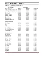
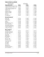
REPLACEMENT PARTS:  

SNR48SC-2, SNR59SC-2 & SNR77SC-2 


Part Description 


Part Number 

Refrigeration System   


SNR48SC-2 


SNR59SC-2 


SNR77SC-2 

Condensing Unit (SC only before 5/1/16) 

30-14218 


30-14218 


30-14219 

Compressor (Replacement before 5/1/16) 

30-15036 


30-15036 


30-15038 

Condensing Unit (SC only after 5/1/16) 

30-20513 


30-20513 


30-14219 

Compressor (Replacement after 5/1/16) 

30-20966 


30-20966 


30-15038 

Evaporator Coil   


33-50053 


33-11499 


33-50037 

Expansion Valve  


32-12625 


32-12625 


32-12625 

Evaporator Fan Motor 


41-11628 


41-11628 


41-11628 

Evaporator Fan Blade 


72-32507 


72-32507 


72-11450 

Filter Drier 


32-12626 


32-12626 


32-12391 

Thermostat 


32-15495 


32-15495 


32-15495 

Thermostat Knob  


72-15447 


72-15447 


72-15447 

Base Service Valve 


32-11723 


32-11723 


32-11723 

Solenoid Valve (Remote Only) 


32-30141 


32-30141 


32-30141 


Electrical Components


Power Switch 


41-11066 


41-11066 


41-11066 

Light Switch 


41-11066 


41-11066 


41-11066 

Terminal Block   


45-11056 


45-11056 


45-11056 

Ballast   


----------  


----------  


39-12902 

Ballast   


39-12904 


39-12904 


39-12904 

Light Bulb 


42-11069 


42-11070 


42-11071 

Light Cord (w/Receptacle)  


43-12269 


43-12269 


43-12269 

Light Cord (w/Plug) 


43-10989 


43-10989 


43-10989 

Light Socket (Stationary)   


42-10834 


42-10834 


42-10834 

Light Socket (Spring Loaded) 


42-10833 


42-10833 


42-10833 

Compressor Receptacle 


45-11677 


45-11677 


45-11677 

Condensate Evaporator 


40-20420 


40-20420 


40-20420 


Misc. Components 

Front Glass 


50-10995 


50-10996 


50-10998 

End Glass- Clear   


50-11115 


50-11115 


50-11115 

Reflective End L.H. 


50-11173 


50-11173 


50-11173 

Reflective End R.H. 


50-11174 


50-11174 


50-11174 

Door L.H.- Clear  


53-11091 


53-11095 


53-11099 

Door R.H.- Clear  


53-11092 


53-11096 


53-11100 

Door L.H.- Reflective 


53-11093 


53-11097 


53-11101 

Door R.H.- Reflective 


53-11094 


53-11098 


53-11102 

Wire Shelf- Top   


63-11025 


63-11028 


63-11031 

Wire Shelf- Middle 


63-11026 


63-11029 


63-11032 

Wire Shelf- Bottom 


63-11027 


63-11030 


63-30242 

Glass Shelf- Top   


52-11214 


52-11217 


52-11220 

Glass Shelf- Middle 


52-11215 


52-11218 


52-11221 

Glass Shelf- Bottom 


52-11216 


52-11219 


52-11222 

Light Shield 


42-30200 


42-15641 


42-15637 

Decal- Slip Hazard 


91-11175 


91-11175 


91-11175 

Thermometer 


32-11068 


32-11068 


32-11068 

Glass Handle 


66-11077 


66-11078 


66-11080 

Clamp (Glass) 


81-11043 


81-11044 


81-11045 

Gas Cylinder 


81-11046 


81-11047 


81-11046 

Pivot Hinge 


66-11076 


66-11076 


66-11076 

Leg Leveler 


65-11486 


65-11486 


65-11486 

Summary of Contents for SNR48

Page 1: ...ined Remote Models INSTALLATION OPERATION INSTRUCTIONS KEEP THIS MANUAL FOR FUTURE REFERENCE Engineering and technical date are subject to change without notice FEDERAL INDUSTRIES PO BOX 290 215 FEDER...

Page 2: ...Doors 12 Anti Fogging Fans 12 Hinged Front Glass 13 Shelves 14 Light Replacement 15 Placing Product into Case 15 Periodic Maintenance 15 CLEANING INSTRUCTIONS 16 Daily Cleaning 16 Weekly Cleaning 16...

Page 3: ...SC 2 SN77 3SC 2 32 WIRING DIAGRAM SN4CD 33 WIRING DIAGRAM SN6CD 34 WIRING DIAGRAM SN8CD 35 WIRING DIAGRAM REMOTE 36 WIRING DIAGRAM SNR48R 2 SNR59R 2 OBSOLETE 1 1 2012 36 WIRING DIAGRAM SNR77R 2 OBSOLE...

Page 4: ...hasing a Federal Industries display case This manual contains important instructions for installing and servicing the Series 90 Refrigerated Bakery Cases A repair parts list and wiring diagram are als...

Page 5: ...The following signal words are used in the warnings and safety messages DANGER Severe injury or death will occur if you ignore the message WARNING Severe injury or death can occur if you ignore the m...

Page 6: ...ur shipment Ask for immediate inspection of your concealed damage item Crating material must be retained to show the inspector from the truck line INSTALLATION INSTRUCTIONS Locating the Display Case T...

Page 7: ...f it is necessary to remove tape residue from plastic materials use cleaning compounds recommended in the cleaning section of this manual Leveling the Case The case must be level for proper drainage o...

Page 8: ...display case are to be supplied by installing contractor C Route properly sized and designed refrigeration lines from the condensing unit to the cabinet Horizontal suction lines should be pitched down...

Page 9: ...vice ports Normally it is not necessary to remove this panel to install the case Condensate Evaporator This case is furnished with an electric condensate evaporator Plumbing connections are not requir...

Page 10: ...ow in the case and cause product loss Close the front glass and reinstall both rear doors Optional Glass Shelves Put the glass shelves on the rear shelf support and shelf light housing as shown The sh...

Page 11: ...l standards A separate circuit for each display case is recommended to prevent other appliances on the same circuit from overloading the circuit and causing malfunction The electrical service must be...

Page 12: ...ensing unit It has an off position and numbered positions 1 through 9 The coldest setting is 9 Set this control at the smallest number while maintaining desired case temperature Thermometer This is a...

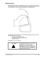
Page 13: ...g of the case interior Pneumatic cylinders assist in lifting the glass The glass will hold in any position beyond approximately the first 20 of travel In the first 20 of travel the glass will gently c...

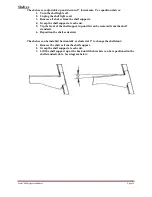
Page 14: ...shelf support at each end 5 Tip the front of the shelf support up until it can be removed from the shelf standard 6 Reposition the shelf as desired The shelves can be installed horizontally or slanted...

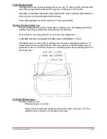
Page 15: ...display pans Overhanging the shelves will block the refrigerated air flow and could cause product loss Do not block the slots along the front or rear of the case display floor CASE SHOULD BE STOCKED...

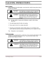
Page 16: ...me Note For major spills or foreign material buildup use complete weekly cleaning instruction 1 Clean all foreign materials from the door opening 2 Wipe complete interior of case using a damp cloth 3...

Page 17: ...d and parts disassembled to allow proper cleaning of the unit 8 Clean all shelves shelf support assemblies shelf standards and display pans using warm soapy water and a brush Rinse thoroughly and allo...

Page 18: ...answers you need faster For Warranty Service Requests ALL Technical Support please contact Phone 800 356 4206 and choose the Tech Support Warranty Option Email Service federalind com For Warranty Com...

Page 19: ...closed c Check for a blocked or dirty condenser coil d Check cold air flow Lack of adequate cold air flow could be a defective evaporator fan or blocked evaporator coil Check that paper or foreign ma...

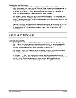
Page 20: ...persons walking by or working in the general area of the case Any case malfunction or housekeeping problem that creates a slip fall hazard around or under a case should be corrected immediately SALE D...

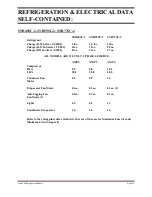
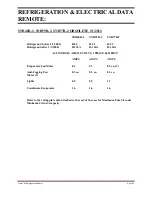
Page 21: ...28 oz Charge R513a after 1 1 2020 21oz 21oz 27 oz ALL MODELS ARE 120 VOLT 1 PHASE 60 HERTZ AMPS AMPS AMPS Compressor RLA 8 8 8 8 10 1 LRA 58 8 58 8 68 0 Condenser Fan 0 5 0 5 1 4 Motor Evaporator Fan...

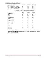
Page 22: ...a after 1 1 2020 19 oz 19 oz 19 oz ALL MODELS ARE 115 VOLT 1 PHASE 60 HERTZ AMPS AMPS AMPS Compressor RLA 8 1 8 1 8 1 LRA 40 0 40 0 40 0 Condenser Fan 0 5 0 5 0 5 Motor Evaporator Fan 0 3 0 3 0 3 Moto...

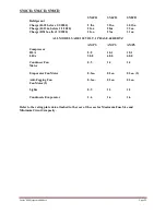
Page 23: ...21oz 27oz 31 oz ALL MODELS ARE 120 VOLT 1 PHASE 60 HERTZ AMPS AMPS AMPS Compressor RLA 8 8 10 1 10 1 LRA 58 8 68 0 68 0 Condenser Fan 0 5 1 4 1 4 Motor Evaporator Fan Motor 0 3ea 0 3ea 0 3ea 2 Anti Fo...

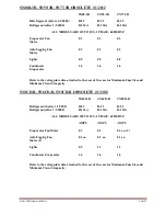
Page 24: ...0 R 22 R 22 R 22 Refrigerant after 1 1 2000 R 134A R 134A R 134A ALL MODELS ARE 120 VOLTS 1 PHASE 60 HERTZ AMPS AMPS AMPS Evaporator Fan Motor 0 3 0 3 0 3 ea 2 Anti Fogging Fan 0 3 ea 0 3 ea 0 3 ea Mo...

Page 25: ...he rating plate data attached to the rear of the case for Maximum Fuse Size and Minimum Circuit Ampacity SN4CD R SN6CD R SN8CD R OBSOLETE 1 1 2012 SN4CD R SN6CD R SN8CD R Refrigerant before 1 1 2000 R...

Page 26: ...1 Light Cord w Receptacle 43 12269 43 12269 43 12269 Light Cord w Plug 43 10989 43 10989 43 10989 Light Socket Stationary 42 10834 42 10834 42 10834 Light Socket Spring Loaded 42 10833 42 10833 42 108...

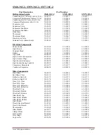
Page 27: ...269 43 12269 Light Cord w Plug 43 10989 43 10989 43 10989 Light Socket Stationery 42 10834 42 10834 42 10834 Light Socket Spring Loaded 42 10833 42 10833 43 10833 Compressor Receptacle 45 11677 45 116...

Page 28: ...ptacle 43 10988 43 10988 43 10988 Light Cord w Plug 43 10989 43 10989 43 10989 Light Socket Stationery 42 10834 42 10834 42 10834 Light Socket Spring Loaded 42 10833 42 10833 42 10833 Compressor Recep...

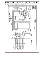
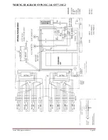
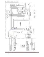
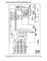
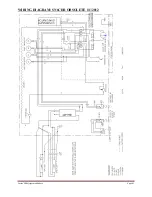
Page 29: ...Series 90 Refrigerated Bakery Page 29 WIRING DIAGRAM SELF CONTAINED WIRING DIAGRAM SNR48SC 2 SNR59SC 2...

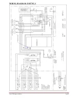
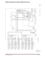
Page 30: ...Series 90 Refrigerated Bakery Page 30 WIRING DIAGRAM SNR77SC 2...

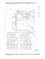
Page 31: ...Series 90 Refrigerated Bakery Page 31 WIRING DIAGRAM SN48 3SC 2...

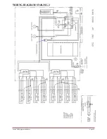
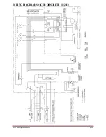
Page 32: ...Series 90 Refrigerated Bakery Page 32 WIRING DIAGRAM SN59 3SC 2 SN77 3SC 2...

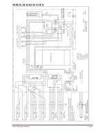
Page 33: ...Series 90 Refrigerated Bakery Page 33 WIRING DIAGRAM SN4CD...

Page 34: ...Series 90 Refrigerated Bakery Page 34 WIRING DIAGRAM SN6CD...

Page 35: ...Series 90 Refrigerated Bakery Page 35 WIRING DIAGRAM SN8CD...

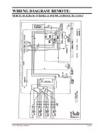
Page 36: ...Series 90 Refrigerated Bakery Page 36 WIRING DIAGRAM REMOTE WIRING DIAGRAM SNR48R 2 SNR59R 2 OBSOLETE 1 1 2012...

Page 37: ...Series 90 Refrigerated Bakery Page 37 WIRING DIAGRAM SNR77R 2 OBSOLETE1 1 2012...

Page 38: ...Series 90 Refrigerated Bakery Page 38 WIRING DIAGRAM SN48 3R 2 OBSOLETE1 1 2012...

Page 39: ...Series 90 Refrigerated Bakery Page 39 WIRING DIAGRAM SN59 3R 2 SN77 3R 2 OBSOLETE 1 1 2012...

Page 40: ...Series 90 Refrigerated Bakery Page 40 WIRING DIAGRAM SN4CDR OBSOLETE 1 1 2012...

Page 41: ...Series 90 Refrigerated Bakery Page 41 WIRING DIAGRAM SN6CDR OBSOLETE 1 1 2012...

Page 42: ...Series 90 Refrigerated Bakery Page 42 WIRING DIAGRAM SN8CDR OBSOLETE 1 1 2012...

Page 43: ...fornia Residents Only WARNING This product can expose you to chemicals including chromium which is known to the State of California to cause cancer and birth defects or other reproductive harm For mor...

Page 44: ...Series 90 Refrigerated Bakery Page 44 REV CHANGE RECORD APP D DATE ECN...

Reviews: