

Series
’9
0 Refrigerated Bakery
Page 27
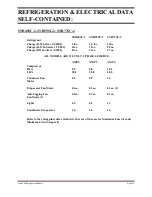
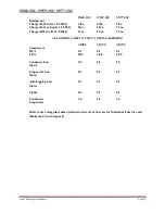
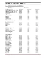
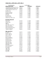
SN48-3SC-2, SN59-3SC-2, SN77-3SC-2
Part Description
Part Number
Refrigeration System
SN48-3SC-2
SN59-3SC-2
SN77-3SC-2
Condensing Unit (SC only before 5/1/16)
30-14217
30-14217
30-14217
Compressor (Replacement before 5/1/16)
30-15034
30-15034
30-15034
Condensing Unit (SC only after 5/1/16)
30-20347
30-20347
30-20347
Compress (Replacement after 5/1/16)
30-20380
30-20380
30-20380
Evaporator Coil
33-12080
33-10992
33-50051
Expansion Valve
32-12625
32-12625
32-12625
Evaporator Fan Motor
41-11628
41-11628
41-11628
Evaporator Fan Blade
72-32507
72-32507
72-32507
Filter Drier
32-12626
32-12626
32-12626
Thermostat
32-15495
32-15495
32-15495
Thermostat Knob
72-15447
72-15447
72-15447
Base Service Valve
32-11723
32-11723
32-11723
Solenoid Valve (Remote only)
32-30141
32-30141
32-30141
Electrical Components
Power Switch
41-11066
41-11066
41-11066
Light Switch
41-11066
41-11066
41-11066
Terminal Block
45-11056
45-11056
45-11056
Ballast
39-18568
39-12904
39-12904
Light Bulb
42-30201
42-11519
42-11519
Light Cord (w/Receptacle)
43-12269
43-12269
43-12269
Light Cord (w/Plug)
43-10989
43-10989
43-10989
Light Socket (Stationery)
42-10834
42-10834
42-10834
Light Socket (Spring Loaded)
42-10833
42-10833
43-10833
Compressor Receptacle
45-11677
45-11677
45-11677
Condenser Evaporator
40-20420
40-20420
40-20420
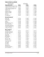
Misc. Components
Front Glass
50-10995
50-10996
50-10998
End Glass- Clear
50-11115
50-11115
50-11115
Reflective End L.H.
50-11173
50-11173
50-11173
Reflective End R.H.
50-11174
50-11174
50-11174
Door L.H.- Clear
53-11091
53-11095
53-11099
Door R.H.- Clear
53-11092
53-11096
53-11100
Door L.H.- Reflective
53-11093
53-11098
53-11101
Door R.H.- Reflective
53-11094
53-11098
53-11102
Wire Shelf- Top
63-11693
63-11696
63-11699
Wire Shelf- Middle
63-11694
63-11697
63-11700
Wire Shelf- Bottom
63-11695
63-11698
63-11701
Glass Shelf- Top
52-12213
52-12052
52-12034
Glass Shelf- Middle
52-12214
52-12053
52-12035
Glass Shelf- Bottom
52-12215
52-12054
52-12036
Light Shield
42-30199
42-15639
42-15639
Decal- Electrical Hazard
91-10743
91-10743
91-10743
Decal- Slip Hazard
91-11175
91-11175
91-11175
Thermometer
32-11068
32-11068
32-11068
Glass Handle
66-11077
66-11078
66-11080
Clamp (Glass)
81-11043
81-11044
81-11045
Gas Cylinder
81-11046
81-11047
81-11046
Pivot Hinge
66-11076
66-11076
66-11076
Leg Leveler
65-11486
65-11486
65-11486
Summary of Contents for SNR48
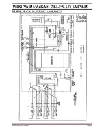
Page 30: ...Series 90 Refrigerated Bakery Page 30 WIRING DIAGRAM SNR77SC 2...
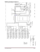
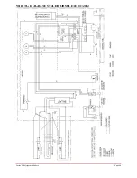
Page 31: ...Series 90 Refrigerated Bakery Page 31 WIRING DIAGRAM SN48 3SC 2...
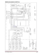
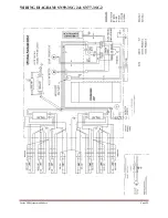
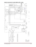
Page 32: ...Series 90 Refrigerated Bakery Page 32 WIRING DIAGRAM SN59 3SC 2 SN77 3SC 2...
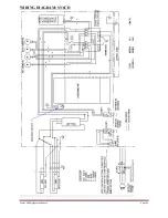
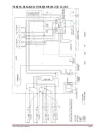
Page 33: ...Series 90 Refrigerated Bakery Page 33 WIRING DIAGRAM SN4CD...
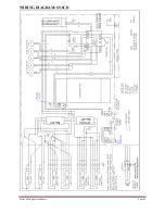
Page 34: ...Series 90 Refrigerated Bakery Page 34 WIRING DIAGRAM SN6CD...
Page 35: ...Series 90 Refrigerated Bakery Page 35 WIRING DIAGRAM SN8CD...
Page 37: ...Series 90 Refrigerated Bakery Page 37 WIRING DIAGRAM SNR77R 2 OBSOLETE1 1 2012...
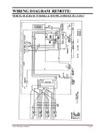
Page 38: ...Series 90 Refrigerated Bakery Page 38 WIRING DIAGRAM SN48 3R 2 OBSOLETE1 1 2012...
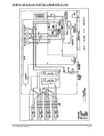
Page 39: ...Series 90 Refrigerated Bakery Page 39 WIRING DIAGRAM SN59 3R 2 SN77 3R 2 OBSOLETE 1 1 2012...
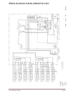
Page 40: ...Series 90 Refrigerated Bakery Page 40 WIRING DIAGRAM SN4CDR OBSOLETE 1 1 2012...
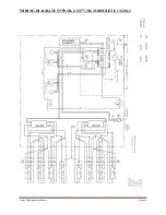
Page 41: ...Series 90 Refrigerated Bakery Page 41 WIRING DIAGRAM SN6CDR OBSOLETE 1 1 2012...
Page 42: ...Series 90 Refrigerated Bakery Page 42 WIRING DIAGRAM SN8CDR OBSOLETE 1 1 2012...
Page 44: ...Series 90 Refrigerated Bakery Page 44 REV CHANGE RECORD APP D DATE ECN...