background image

FeelTech


FY6600 Series User

’s Manual                                                                                   

25


Burst 


FY6600 can output waveform with specified number of cycles (called Burst) 

from the CH1 channel. FY6600 supports control of burst output by CH2(internal), 
manual or external trigger source; The signal generator can generate burst using 
Sine wave, Square wave, Ramp wave, Pulse, Noise wave or arbitrary waveform 
(except DC). 


The  instrument  supports  [CH2],  [external]  and  [manual]  three  trigger  output  modes,  which 

can be selected by the corresponding keys.


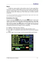
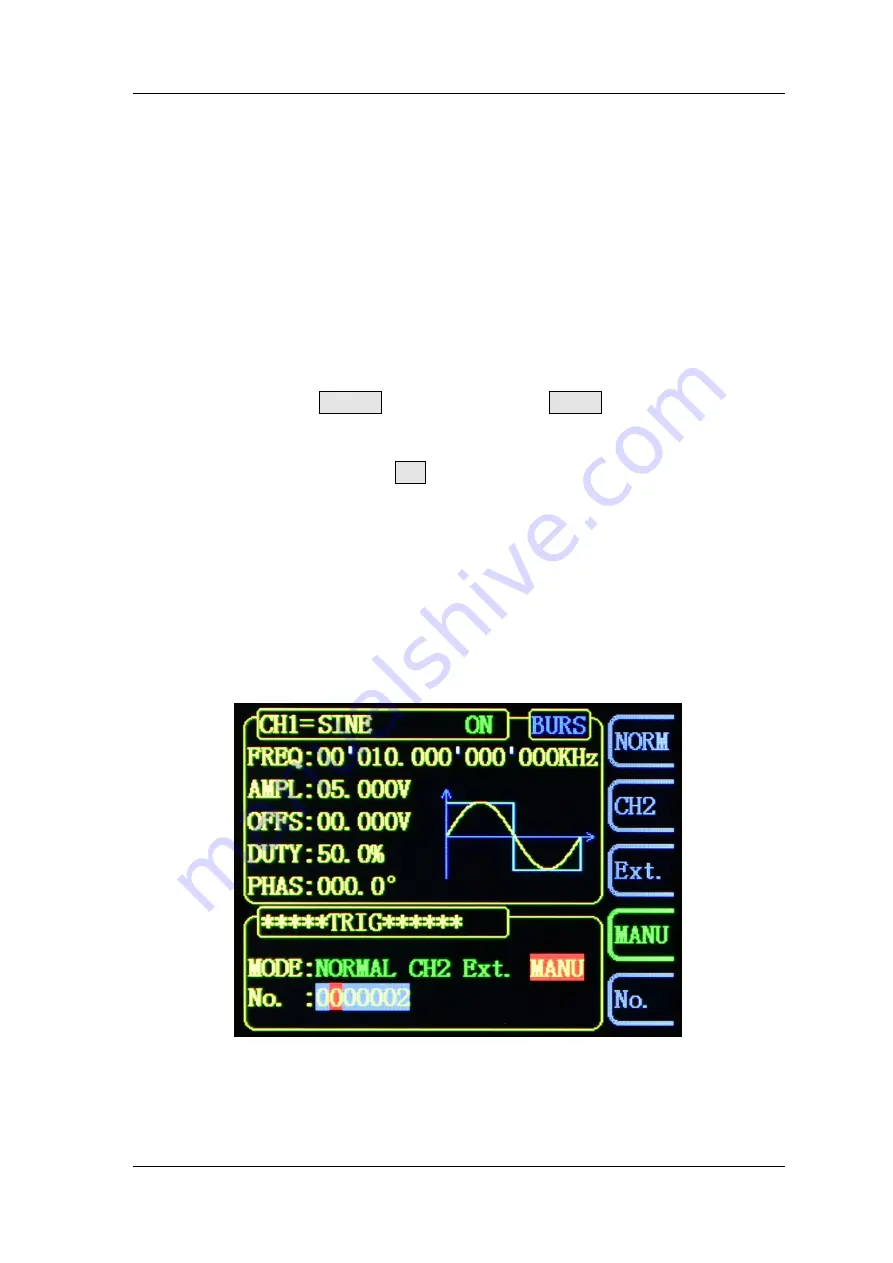
Enable Burst Function


Press  the  front  panel 

BURST

  button,  then  press 

BURS

  button  to  enter  burst 

function.  The  instrument  supports  [CH2],  [external]  and  [manual]  ,  three  trigger 
output  modes,  which  can  be  selected  by  the  corresponding  button.  When  the 
burst function is enabled, press 

No.

 button to set the cycles of burst. Use arrow 

buttons and ADJ Knob to set the numbers from 1 to 1048575. Then the generator 
will output burst waveform according to current configuration. 
 

  NORMAL: The Burst function is disabled


  CH2 Trigger: CH1 will generate a burst when CH2 generates a pulse. 

  Ext. Trigger: CH1 will generate a burst when EXT.IN connector was inputted a 

pulse.   

  MANU Trigger: User can trigger a burst by pressing ADJ Knob (OK button). 


Summary of Contents for FY-6800

Page 1: ...FeelTech FY6600 Series Fully Numerical Control Dual Channel Function Arbitrary Waveform Generator User s Manual Rev2 2 July 2017...

Page 2: ......

Page 3: ...n in this publication replaces all previously corresponding material FeelTech shall not be liable for losses caused by either incidental or consequential in connection with the furnishing use or perfo...

Page 4: ...et Amplitude 18 Set Offset 19 Set Duty Cycle Square Set pulse wave pulse width Adj Pulse 20 Set Phase 21 Enable Output 22 Example Output Sine Waveform 23 Burst 25 Frequency Meter Counter 27 Enable the...

Page 5: ...ability of signals Surface mounting technology improves interference immunity and operational life span This instrument has double channels can output 31 preseted DDS signals including Sine Square Tri...

Page 6: ...ers the next boot automatically load the saved parameters Complete independent dual channels can work at same time and phase difference is adjustable Following function allows users to synchronize all...

Page 7: ...p types Sweep time can be up to 999 99S Sweep starting point and end point can be set arbitrarily It has pulse train burst output function There has Manual Trigger internal CH2 Trigger and External Tr...

Page 8: ...t Output short circuit protection All channels can work more than 60 seconds when the load is short circuited Can choose our FYV2000 series or FPA1000 series power amplifier to output 20W or higher si...

Page 9: ...shipment have been checked for completeness and the instrument has passed both electrical and mechanical tests The consigner or carrier shall be liable for the damage to instrument resulting from ship...

Page 10: ...h DC and AC are workable Gate Time can be 1S 10S or 100S Dual channels output and measurement function can work together at same time Can sweep Sine Square Arbitrary and so on Can sweep frequency ampl...

Page 11: ...atus Press ADJ Knob to Start Stop sweep under Sweep interface 7 Power Button The power indicator keeps illuminating when power on Press the power button and the indicator change to notifylight status...

Page 12: ...l output connector CH2 connector output impedance is 50 When CH2 channel activates indicator illuminates CH2 outputs signal with parameters set 11 AC coupling measuring terminal BNC connector input im...

Page 13: ...al can realize voltage controlling frequency voltage controlling amplitude voltage controlling offset voltage controlling duty cycle and so on Frequency of external signal input should be lower than 5...

Page 14: ...anual Warning To avoid instrument damage voltage of signal input from EXT IN CANNOT exceed 20Vac dc Voltage of signal input from Trig FSK ASK PSK IN CANNOT exceed DC5V Note To ensure the normal work p...

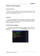
Page 15: ...s than 5W Power On Turn on the power switch after the power cord is connected The generator will execute self inspection The LCD will show welcome interface after the inspection is over If the generat...

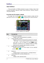
Page 16: ...tion 1 Current channel selected Display current channel selected for operation 2 Current waveform selected Display the name of current waveform selected For example CH1 Sine means current waveform sel...

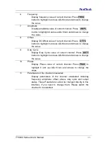
Page 17: ...t and use ADJ Knob and Arrows to change the value 9 Duty Cycle Display Duty Cycle value of current channel Press DUTY button to highlight it and use ADJ Knob and Arrows to change the value 10 Phase Di...

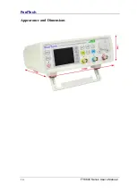
Page 18: ...FeelTech 14 FY6600 Series User s Manual Appearance and Dimensions...

Page 19: ...figure the instrument to output various waveforms Select Output Channel CH1 and CH2 buttons are used to change current channel selected At start up CH1 is displayed on the top with yellow color and CH...

Page 20: ...e Half Wave Rectification Negative Half Wave Rectification User defined waveform Press WAVE to change waveform selected Or rotate ADJ Knob under waveform switching status to change waveform The wavefo...

Page 21: ...cy are different For detailed information please refer to Frequency in Specifications The default frequency is 10kHz Press FREQ button to highlight value of Frequency Then use Arrow buttons and ADJ Kn...

Page 22: ...Points 1 What s the difference of amplitude in Vpp and the corresponding value in Vrms Answer Vpp is the unit for signal peak peak value and Vrms is the unit for signal effective value The default un...

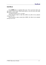
Page 23: ...n and ADJ Knob to set the value Press Arrows button to move the cursor and rotate ADJ Knob to set the value The offset accuracy is 1mV i e 0 001V When frequency output is lower than 20MHz the offset c...

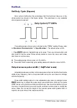
Page 24: ...tting range of duty cycle is 0 1 99 9 Press ADJ Knob under duty cycle setting status will initial the value to 50 Set pulse wave pulse width Adj Pulse wave Adjustable pulse wave refers to the square w...

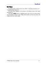
Page 25: ...olution is 0 1 The default phase value is 0 The start phase displayed on the screen is the default value or the phase previously set Then press PHAS button to highlight phase value Then use Arrows but...

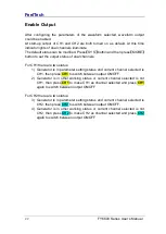
Page 26: ...or is in parameter setting status and current channel selected is CH1 then press CH1 to switch between output ON OFF 2 Generator is in other working status or current channel selected is not CH1 then...

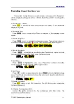
Page 27: ...DJ Knob to get 2 FREQ 00 020 000 000 000kHz 4 Set the Amplitude Press AMPL to highlight the amplitude value Press Arrow buttons to move the cursor and rotate the ADJ Knob to get the figures below AMPL...

Page 28: ...FeelTech 24 FY6600 Series User s Manual...

Page 29: ...nction Press the front panel BURST button then press BURS button to enter burst function The instrument supports CH2 external and manual three trigger output modes which can be selected by the corresp...

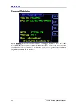
Page 30: ...Press BURST button to enter numerical and trigger function then press the relevant button to enter relevant modulation function Modulation mode can be external modulation and manual modulation Modulat...

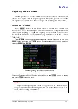
Page 31: ...AC coupling or Trig IN DC coupling The result will be displayed on the screen in real time The lowest frequency workable is 0 01 Hz GATE TIME 100S Press COUN button to enter external pulse counter fun...

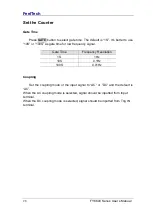
Page 32: ...as gate time for low frequency signal Gate Time Frequency Resolution 1S 1Hz 10S 0 1Hz 100S 0 01Hz Coupling Set the coupling mode of the input signal to AC or DC and the default is AC When the AC coupl...

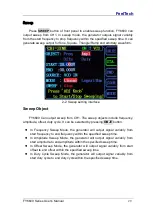
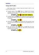
Page 33: ...jects include frequency amplitude offset duty cycle It can be selected by pressing OBJE button In Frequency Sweep Mode the generator will output signal variably from start frequency to end frequency w...

Page 34: ...000 000 000kHz Amplitude Sweep Press STAR button to highlight start amplitude parameter Press the Arrow buttons and rotate the ADJ Knob to set the specified value For example START 10 00V Offset Sweep...

Page 35: ...20 000 000 000kHz Amplitude Sweep Press END button to highlight end amplitude parameter Press the Arrow buttons and rotate the ADJ Knob to set the specified value For example END 20 00V Offset Sweep P...

Page 36: ...can realize voltage controlling frequency VCF voltage controlling amplitude VCA voltage controlling offset voltage controlling duty cycle and so on Operation method Press SWEEP button to enter sweep f...

Page 37: ...End value Start value Sweep time 100 Logarithm Sweep In linear sweep type the signal parameter varies logarithmically For example in the frequency sweep the output frequency changes in the way of octa...

Page 38: ...rator sweeps from low frequency to high frequency Start Frequency End Frequency the generator sweeps from high frequency to low frequency Start Frequency Stop Frequency the generator outputs with a fi...

Page 39: ...of waveform to save positions 20 sets LOAD To load parameters to current working status from save positions CONF To set system language turn on off Buzzer and Uplink mode MORE To set default output s...

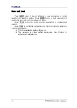
Page 40: ...load parameters of waveforms previously set to current system status Select S xx on the right to save current parameters to corresponding position Select L xx on the right to load parameters from cor...

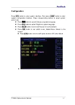
Page 41: ...e Press corresponding buttons to select system work mode Press button to select Chinese as system language Press Eng button to select English as system language Press BUZZ button to turn on off buzzer...

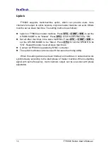
Page 42: ...o set the UPLINK to be ON Set all other machines to be slave machines Press SYS CONF M S to set the UPLINK MODE to be Slave Press UPLI to set the UPLINK to be ON Repeat this step to set all slave mach...

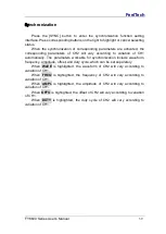
Page 43: ...ically The parameters workable for synchronization include waveform frequency amplitude offset and duty cycle which can be set separately When WAVE is highlighted the waveform of CH2 will vary accordi...

Page 44: ...instrument after finishing the above inspections 4 If it still does not work correctly please contact FeelTech CH2 is locked 1 Check that the signal generator is operating in synchronous state Press...

Page 45: ...models of pulse wave minimum width can reach 20ns Min Resolution on all frequency range 1 Hz Min resolution can reach 1 Hz on all frequency range to ensure adjusting accuracy under high frequency For...

Page 46: ...20MHz 1mVpp 5Vpp Amplitude Resolution 1mV Amplitude Stability 0 5 5 Hours Amplitude flatness 5 10MHz 10 10MHz Waveform Output Impedance 50 10 Typical Protection All channels can work more than 60 seco...

Page 47: ...rameters Range Starting position and Finishing position can be set arbitrarily Sweep Range Decided by Parameters setting VCO Voltage Control Output Modulation signal range to input 0 5V VCO signal fre...

Page 48: ...value Interface Type USB to Serial interface Communicati ng Speed 9600bps Industrial standard Protocol Command line mode protocol complete open Power Voltage Range AC100V 240V Technic SMD LSI Reliabl...

Page 49: ...arameter of the technical indexes in this manual should be referred to If this suggestion is not obeyed death or serious personal injury could be caused In this condition the company will not be respo...

Page 50: ...duct is proven to be defective within the respective period FeelTech guarantees the free replacement or repair of products which are approved defective This product enjoy 1 year warranty since its del...

Reviews: