9
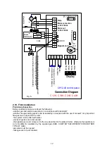
-DWT thermistor
-display
Jumper can be found:
-between points 8 and 9
-and 10 and 11
2. 7 Connecting of room thermostat:
For operation of the boiler the room thermostat must be connected.
-Remove jumper between points 8 and 9.
-Wire up to points 8 and 9 the heating operating contacts of room thermostat.
If proper operation of room thermostat needs mains voltage 230V than from point 7 the neutral
conductor must be connected to the room thermostat. (At point 8 mains phase is located and at point
9 phase must appear only in case of request for heating).
Notes: (1) In relation to conductors phase and neutral see notes (*) under Table 1.
(2) Short circuit caused by false connecting of room thermostat results in blowing of 100mA
fuse marked F2. After proper connecting and change of fuse the circuit will be ready to operate.
-Optionally connectable:
a) Lock (e.g.: switch clock, timer, chimney damper, water heater lock, etc.) between points 10 and 11.
For this first remove the jumper.
b) For an appliance with low current input (e.g.: Floor heating module, electronic temperature
controller, etc.) mains input can be connected from points 5 and 6 (which inputs stop when the mains
plug of boiler is disconnected).
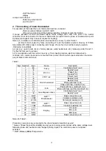
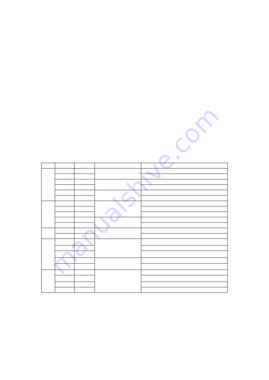
Table 1.
Sign Number Sign
Name
Description
1 Lsz
Controlled
phase*
(out)
2 N
Pump
Neutral* (out)
3 L
Phase*
(in)
4 N
230 V in
Neutral* (in)
5 L
Phase*
(out)
J1
6 N
230 V out
Neutral* (out)
7 N
Neutral*
(out)
8
Lth
Phase with fuse* (out)
9 Lk
Room thermostat
Phase with fuse, switched* (in)
10
Lk
Phase with fuse, switched* (out)
J3
11 Lr
Lock
Phase with fuse, switched and lock* (in)
12 Lg
Controlled
phase*
(out)
J2
13 N
Gas Magnetic Valve
Neutral* (out)
14
GND
Base connection (out)
15
+VAR
Variable resistance (out)
16 +C
ON
DWT**
Potentiometer
Permanent resistance (in)
17
GND
Base connection (out)
J4
18 +VAR
DWT**
Thermistor
Variable resistance (in)
19
+5 V
+5 V (out)
20 SCL
SCL
(out)
21 SDA
SDA
(out)
J5
22 GND
Display
Base connection (out)
Notes for Table 1.:
Protection conductors are connected to the shock hazard protection bus wire!
* Names "Phase"
(L)
and Neutral
(N)
are only given to make points defined at the same voltage level.
Naturally phase and neutral can be changed (during input)! The electronic panel is not phase-
sensitive.
** DWT=
D
elivery
W
ater
T
emperature

