background image


-Between 1750-3140 W/m³ specific load the room must be ventilated to another room by 2 pcs. of 
non-lockable vents. The cross section of these must be at least 1510 cm² and there must be a 
minimum of 1,8 m vertical distance between them. In this case the next parameters have to be 
realized:  

-total specific load must be under than 1250W/m³. 
-total cross section (of door or window) opening to open air or staircase must be 1,3m². 
-a card prohibiting covering of vents is to be placed in the room. Under 1750W/m³ specific load 
there is no need for airing if the room has a door opening to open air or a window bigger than 
1,3 m² or the door opens to a room having this kind of window. Otherwise ventilation is to be 
realized according to points a) and b). (The shut-off device must not be leakproof). 
 
With the exception of bedroom and rooms for constant stay the appliance can be installed in 
any kind of room if the following conditions are realized in case of an opened combustion 
chamber: 

-maximum vertical distance between the boiler and the chimney is 0,2 m. 
-vertical distance of lower edge of the boiler from the floor must be 0,4-1,4 m. 
-operation and repairability must be ensured. A space of 0,1 m on the sides and 0,8 m on 
the front must be left. 
-the boiler can only be mounted on a wall made of non-burnable materials (thickness of 
wall must be a min. of 0,1 m.) 
-gas equipments must not be installed above each other. 
-two gas equipments (in one room) can be joined the same chimney provided the vertical 
distance of their connections is min. 0,3 m and neither of the appliances exceeds 35 kW 
nominal heating capacity. 
-it is recommended to make between the upper edge or the deflector of the appliance a 
chimney intake, which length is triple of the diameter of the chimney. 
-if the boiler is placed into a cabinet, then it is to be built from floor to ceiling, its walls and 
door must be made of non-burnable material. If possible, its door should be gridded. 


2.4. Flue gas piping 

Designing, implementing, method of connecting, dimensioning chimneys are specified by standards of 
building. The appliances can be connected to a chimney permitted by the chimney-sweeping 
companies. The chimney has to be gas-proof. 
A boiler can be installed even in a cellar provided the room is damp-proof and has a solid floor. 

-smoke tube must be resistant against mechanical effects (aluminium tube is suitable). 
- smoke tube is to be resistant against temperature of flue-gas and accompanying 
condensation. 
-max. horizontal piping of smoke-tube is 2m. 
-diameter of smoke-tube can not be smaller than the connection stub of deflector. 
-cross section of quadrangular chimneys must be 10% more than the connection stub of 
the appliance. 
-above deflector there must be a min. of 3D long straight section. (Hungarian standard). 
-material of smoke-pipe should be aluminium sold in trade.  

 
Placement of boilers operated by PB gas 

The appliance must not be placed in: 
-a cellar if all of its walls and its floor are under ground level. 
-a building made of panel units. 
-a residential building if there is a cellar or subground floor in it. 
-specific weight of PB gas is higher than of air so the general rule is that gas should not be able to set 
in druses and canals because it may explode. 
 

Attention 

The boiler has got a flue-gas backflow sensor. When it starts operation the boiler stops automatically. 
Restart can only be made by manual ignition of pilot flame. 

Disabling, damaging and/or demounting of safety system is prohibited!


In case of repeated failures a skilled serviceman must check the chimney. 

The producer is not liable for damages caused by faults of installation, incorrect use, changes 
made in the appliance or neglecting manufacturer's instructions and valid regulations. 

Summary of Contents for C 24 H

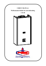
Page 1: ...USER S MANUAL Wall mounted boiler for central heating C 24 H F t stechnikai K sz l kgy rt Ltd Hungary 6900 Mak Aradi street 136...

Page 2: ...4 FLUE GAS PIPING 7 2 5 FILLING AND PUTTING INTO OPERATION 8 2 6 ELECTRIC DESCRIPTION 8 2 7 CONNECTING OF ROOM THERMOSTAT 9 2 8 INSTALLATION 10 2 9 FROST PROTECTION 11 2 10 FIRST INSTALLATION 12 2 11...

Page 3: ...electric appliance do not move any electric wall plug do not employ an open fire In case of further gas leakage turn off the main gas valve under the gas meter The gas leakage must be reported to the...

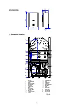
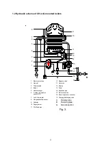
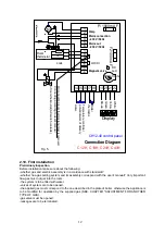
Page 4: ...Pilot flame holder Flue gas backflow sensor Limiter thermostat Pump Electric control box Purging screw Thermocouple Gas inlet pipe 19 20 Thermistor Display A G B Delivery water Gas connection Returni...

Page 5: ...s inlet 3 Thermocouple 4 Burner 5 Heat exchanger 6 Delivery temperature sensor NTC 7 8 Flue gas backflow sensor Limiter thermostat 9 Deflector 10 Purging screw 11 11 Pilot flame pipe 12 12 Magnetic va...

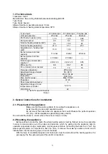
Page 6: ...temperature controller 5 30 C Weight kg 22 At 15 C and 1013 mbar Table 1 2 General instructions for installation 2 1 Placement of the appliance Make sure that the wall is suitable for mounting the app...

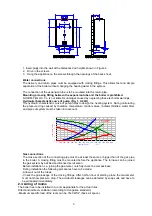
Page 7: ...nt Gas connections The cross section of the connecting pipe must be at least the same or bigger than of the gas pipe in the boiler A closing fitting must be mounted before the appliance The furnace ca...

Page 8: ...if the boiler is placed into a cabinet then it is to be built from floor to ceiling its walls and door must be made of non burnable material If possible its door should be gridded 2 4 Flue gas piping...

Page 9: ...hed wall socket placed beside the appliance or in case of a bathroom in zone 3 and connect it to the electric network of the house Max current drain of the boiler is not bigger than 1Amper Attention T...

Page 10: ...rent input e g Floor heating module electronic temperature controller etc mains input can be connected from points 5 and 6 which inputs stop when the mains plug of boiler is disconnected Table 1 Sign...

Page 11: ...a request for heating on the part of room thermostat Turn potentiometer located on electronic panel and marked P1 by a screwdriver while checkig the display As a result of adjustment display changes f...

Page 12: ...in burner Cause of failure can be Minimum required quantity of water is not provided Temporary lack of water in the leaking heating system Notes Above 91 C the electronics consider thermistor dead sho...

Page 13: ...ce is to be modified for operation by the supplied gas SEE CHAPTER ADJUSTMENT FOR ANOTHER TYPE OF GAS gas valve must be opened leakages are to be terminated Mains 230V IN 1 2 3 4 7 8 9 10 11 12 13 141...

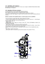
Page 14: ...n order to adjust the combined gas valve correctly follow the next steps Connect a pressure gauge to stub C after loosening of closing screw Pressure of connecting gas can be measured on stub E in cas...

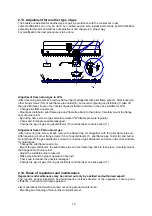
Page 15: ...r 10 and the label on back panel 11 Adjustment from LPG to natural gas After loosening the screw M 4x8 remove the flame trap 3 altogether with the pilot flame pipe 4 After loosening of other fixing sc...

Page 16: ...er is PROHIBITED Maintenance is not an action of guarantee 3 Instructions for use and maintenance for users First installation of the appliance may only be made by an expert of the service network of...

Page 17: ...rotective heating operates until 25 C DWT Reaching this value the boiler stops after 1 minute of post circulation Notes frost protection starts to operate only when the gas supply of boiler is ensured...

Page 18: ...pliance every five years ATTENTION The boiler has got a flue gas backflow sensor When it starts operation the boiler stops automatically Restart can only be made by manual ignition of pilot flame Disa...

Reviews: