8
2.5. Filling and putting into operation
Filling must be carried out by soft water. Before starting filling every valve must be opened and the
outlet valves must be closed. Air discharging valves are to be opened and ensure that the caps of
automatic ones' are opened to 1-2 turns.
Filling must be done slowly. Keep an eye on lower situated purging points and purging valves of
radiators and close them after the appearance of water. Automatic purgers' caps must not be closed!
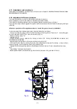
Purging of pump can be done by unbolting the screw on the front of it. Purging of boiler can be done
during slow filling by air discharging valve situated on heat exchanger.
Technicalness is very important from the point of long operation life. Frequent charging or discharging
of the system or certain parts of it and other water losses (leakages) cause consequential refill. This
means letting corrosion causing oxygen into the system. If water quality is not suitable than scaling
occurs.
It is recommended to carry out first heating-up slowly (approx. in 5 hours) in the interest of scaling
reduction and perfect purging.
First month purge the system in warm status during continuous refill to let aggregated air out
of the pipes.
2.6. Electric description
(This chapter describes information only about the electric part of boiler. It does not contain hydraulic,
gas technical and installation tasks connecting to the operation of electric unit!)
Preparations for installation
For operation of the appliance the supply voltage is 230V 50Hz. The boiler has a 2m long connection
cable. The user has to provide a two-pole earthed wall-socket placed beside the appliance-or in case
of a bathroom in zone 3-and connect it to the electric network of the house. Max. current drain of the
boiler is not bigger than 1Amper.
Attention!
The user has to arrange mounting, connecting, shock-hazard protection and fire prevention inspection
of the wall plug.
The user also has to provide a room thermostat and its mounting to the suitable place from heating
technical and control engineering point of view as well as a connection cable pulled out from the boiler
to the room thermostat. For a connection cable the most appropriate one is a three-conductor cable
with a nominal voltage of min. 0,4 kV and with a cross-section of 1mm² for each wire. Pull this cable to
the room thermostat without interruption.
The controlling electronics located behind the boiler casing are mounted in a sealed plastic box. Their
protection ratio is IP 44. In case of boilers where the casing cannot be opened (but the case can be
taken off) the protection ratio of the (whole) appliance is IP 45, so if it mounted in a bathroom it can be
placed to zone 1. (According to Hungarian Standard).
After removing boiler casing and cover of controlling box the wiring points can be reached.
Attention!
After removing the cover of control box the points conducting mains voltage (230 V) can be touched!
Therefore:
(1) Removal of cover and connecting (e.g.: the room thermostat) from the box is allowed only in no-
voltage state: the mains plug must be pulled out of the wall-socket.
(2) Adjusting in a voltage state of trimmer potentiometer located in electronic panel must be done by
an insulated screwdriver.
(3) Steps described in points (1) and (2) can be carried out by an electrician!
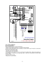
Items in the control box wired up by factory (see Fig. 5.):
-pump
-gas magnetic valve
-DWT potentiometer

