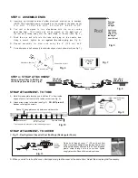
STEP 3: ASSEMBLE ENDS
Fig. 5
Fig. 6
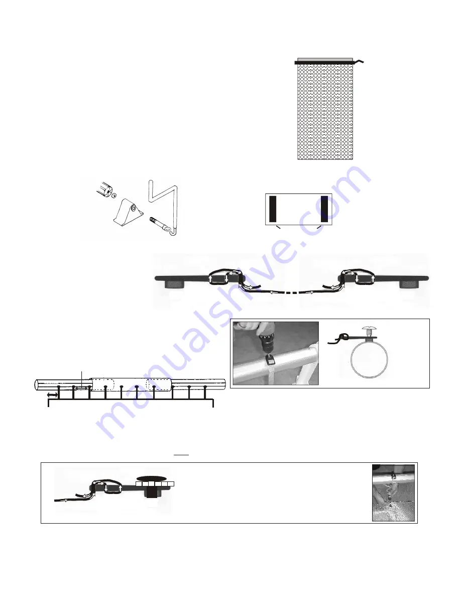
Insert eye bolt through outside of pillow block and wind nut up to bearings.
(NOTE: The FeherGuard name is imprinted on the outside of the pillow block.)
D O N O T T I G H T E N N U T A G A I N S T B E A R I N G S .
T h e r e e l i s d e s i g n e d t o t u r n
c l o c k w i s e
w i t h t h e c o v e r c o m i n g
over the top.
The handle end will be placed on the
right
end of
the reel when facing away from the main length of the pool (see Fig. 5).
Wind the eye bolt fully into the tube end plug at the handle end.
Using a wrench, tighten the nut
against the tube plug
(see Fig. 6).
R e p e a t a s s e m b l y f o r o t h e r e n d u s i n g t h e 5 “ ( 1 2 . 5 c m ) b o l t .
Cut rubber pads in half and apply to underside edges of each pillow block (see Fig. 7).
Position
handle
on right
(reel turns
clockwise
with cover
reeling in
over tubes)
Pool
Eye Bolt #FG-410
FG3 Handle #FG-611
Pillow Block #FG-203
Underside
of Pillow
Block
Rubber pads
A.
B.
C.
D.
E.
Fig. 7
A.
Tube
Fig. 9
Metal Self-Drilling
Screw
Mark first strap plate locations on a drill line 6“ in from inside
edges of pool or at the start of a radius corner (see Fig. 9).
Attach strap plates to the tube (see Fig. 9).
DO NOT pre-drill
holes
or over-tighten screws.
Square corner Square corner
First strap plate is placed 6“ in from inside edge of pool.
Space 10 strap plates evenly between outside marks
Pool
B.
Fig.11 - Reel Systems Placed at Pool End Only (Rectangular Pools)
Cover
(bubbles
down)
Fig. 11
Plastic Screw
Strap end
C.
Strap Plate
Fig. 8
6“
STRAP ATTACHMENT - TO COVER
Pierce hole through cover, 1“ (2.5 cm) back from
edge of cover and straight down (perpendicular) from
a strap plate already attached to tube. Push threaded
plastic screw through hole in cover then tighten
snugly into plate. Repeat for remaining straps.
Strap end
Strap end
Fig. 10
STEP 4: STRAP ATTACHMENT
Attach a Strap Plate to EACH end
of all Straps provided (see Fig.8).
Cover End
Strap Plate
Strap
Tube End
Strap Plate
Strap
Plate
with
Strap
D.
When you start to roll up the cover, all straps must grab the cover at the same time. Adjust the strap lengths if necessary.
STRAP ATTACHMENT - TO TUBE

