background image

Fei Bao Hawker Hunter

Thank you for buying our large scale Hawker Hunter, which has been developed to be quick to
assemble and a pleasure to own and fly. The Hunter is a large, heavy and sophisticated model and as
such it is vital that great care and attention is taken during assembly to ensure a safe and reliable
airframe. You have invested a significant sum in your model so it is false economy to use any items
to complete the aircraft that are not of the quality required; this covers everything from adhesives,
through turbine, radio equipment and on-board power supplies etc. If at any point during the
assembly you are in any doubt about the next step to take please contact the dealer where you
purchased your Hunter – turbine powered models are not the place for guesswork!

It is highly recommended that you carefully inspect all parts of your Hunter before starting assembly,
if there appear to be any faulty parts or items missing please contact your dealer for
advice/replacement. If you have not built a large scale turbine model until now we suggest that you
find a local modeller who has and ask them to act as a mentor/second pair of eyes, to ensure the
model is assembled to the highest standards.

Be aware that depending on the turbine being used, the on-board radio equipment, batteries being
used etc that the model will probably weigh more than 20Kg without fuel, or 25 Kg with fuel, and
that certain countries have restrictions or procedures in place for models over these limits. If you are
unsure of the regulations in place in your country please contact your national modelling authority
for guidance.

When the model is ready to fly we strongly suggest finding a site with a long hard surface runway,
even if this means travelling some distance. Many models have been destroyed on their first flight
due to a take-off or landing incident on a short runway, often due to overshooting on the first
landing, when a turbine takes several seconds to accelerate from idle to full power. Having a long
runway available eliminates this risk and reduces the stress level on the pilot, allowing him to
concentrate more on flying the model. If you have never flown a highly loaded swept wing scale jet
please consider the option of getting a pilot that is experienced in this type of model to carry out the
first flight – this allows the model to be trimmed correctly before you take control.

Parts listing:

Forward Fuselage Section w/Canopy & Hatch
Rear Fuselage Section
Right Wing Panel w/Aileron & Flap
Left Wing Panel w/Aileron & Flap
Tailplane w/Elevators
Fin/Rudder
Intake Ducting
Fuel Tank Set
Control Accessories
Scale Small Parts

Optional Parts:

Summary of Contents for hawker hunter

Page 1: ...depending on the turbine being used the on board radio equipment batteries being used etc that the model will probably weigh more than 20Kg without fuel or 25 Kg with fuel and that certain countries h...

Page 2: ...with great success Servos The Hunter requires a total of 7 high quality servos for the flying surfaces and a further metal geared high power servo for nose wheel steering The prototype model used meta...

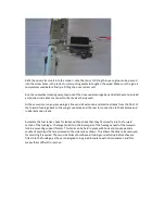
Page 3: ...slot neatly Fit the elevator servo to the hatch making sure all screws are completely tight Fit a suitable length extension lead to the elevator servo it is highly recommended that a heavy duty lead...

Page 4: ...nd depth using Permagrit files be VERY careful to clean out the slot only as far as required and make sure not to cut into the inside of the top skin of the elevator do NOT break through the skin Chec...

Page 5: ...or full and free travel making sure that the servo arms or pushrods cannot jam in any position It may be necessary to bend the pushrods slightly to allow adequate clearance to the end of the slots in...

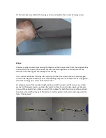
Page 6: ...tightened and consider using a threadlock compound The rudder linkage is internal see photos below Fit the rudder complete with linkage to the fin and then install the rudder servo as show finally cen...

Page 7: ...allen screws used on the landing gear units and oleo legs are checked use of a threadlocking compound on all these screws is suggested whilst the landing gear is removed from the model Fit extension...

Page 8: ...three air ram operated doors these all remaining open the entire time that the retracts are extended Forward Fuselage Initial Assembly Remove the nose retract unit in the similar manner to the mains...

Page 9: ...orward fuselage back to the wing mount area and the rear for connection to the tailplane and rudder extension leads Assemble the fuel tanks check for leaks and then check that they fit correctly into...

Page 10: ......

Page 11: ...embled due to lack of access The extension leads for the rudder and tailplane servos should be retained to the fuselage sides so that they are well away from the tailpipe using commercial servo lead m...

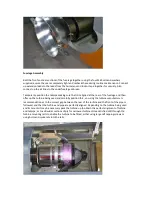
Page 12: ...Fit the mounting lugs to the bellmouth section of the tailpipe and slide the tailpipe into the rear section of the fuselage...

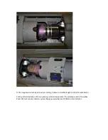
Page 13: ...elage and then offer up the turbine being used and carefully position this ensuring the turbine manufacturer s recommendation as to the correct gap between the rear of the turbine and the front of the...

Page 14: ...for the screws then fit these screws to secure the tailpipe Fit all remaining extension leads and electrical cables including those for the wing connections the following photo shows a typical connect...

Page 15: ...d cutting it down to suitable length to allow for installation Continue the installation of the remaining on board equipment the prototype used a PowerBox Royal SRS twin receiver battery system being...

Page 16: ......

Page 17: ...as possible a former can be glued into place in the forward fuselage as shown and a battery plate made up that slots into this and which is retained at the rear with a couple of bolts glued through t...

Page 18: ...If the Sabrinas are to be fitted the areas of fuselage that these are glued to should have the paint removed as should the base of the Sabrinas before they are carefully glued into place...

Page 19: ...by an electric actuator or air ram this prototype using the air ram method with a simple bellcrank arrangement to increase the travel to the required amount A cross beam system was used to equalise th...

Page 20: ...d forward through the access provided by the open canopy until the pins come free of the holes and then the rear of the scale cockpit can be dropped before this can be carefully withdrawn through the...

Page 21: ...y out any required trimming then use the remainder of the first flight to get comfortable with the flying characteristics and the slow speed handling trying out the effects of flap deployment Keep a r...

Reviews: