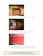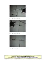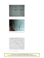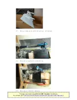
before attaching the fin to the rear fuselage.Secure the
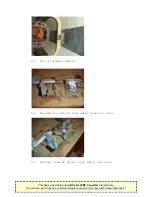
fin rear shaft in the fitting and tighten the hex screw.
The forward attachment shaft also slides into its fitting
and is then secured from the inside of the fuselage with
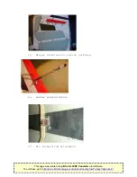
the screw and washer that you tested. Route the servo
lead with its extension attached (and locked)to the
cockpit area and protect the lead in the tail pipe area
with aluminium tape.
6.
Fuel. Inspect the brass fuel lines and clear any burrs on
the inner and outer ends. Check that the clunk reaches
everywhere in the tank and does not get caught anywhere
in the tank. Leak test the tank and check the fit in the
fuselage. Use Velcro tape or your preferred method to
keep the tank in place. I fitted the air trap tank on the
fuselage floor between the retracted main wheels in a 45
degree attitude as recommended. The fill fitting is on
top of the plywood shelf behind the intake. Use brass
tube between the fuel tank and the UAT air trap tank to
avoid fuel line kinking issues.
7.
Engine.Check the glue joints of the engine bearers and
reinforce if needed.The exhaust pipe position depends if
you have a ducted orunducted installation. Mine is
unducted and the exhaust pipe is 10mm from the rear of
the engine exhaust cone. Cut off the excess pipe if
needed. Make sure you center the inner and outer pipe
again.Also make a support for the pipe at the bottom
front. I used flattened brass tubing fitted with screws
to the front lower part of the pipe and the closest
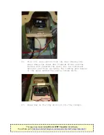
former between the main landing gears. The ECU is fitted
in the space behind the right hand engine air intake. The
engine auxiliary equipment is fitted on brackets above
the engine bearers to the front of the engine.The ECU
battery goes in the nose as needed for the correct CG.
The fuel pump is fitted on a plywood plate on the left
hand side fuselage. Connect all wires and fuel lines.
Tidy up all wire in the engine compartment area as loose
wires might cause problems if they do get sucked into the
engine!! If you use plastic cable ties do not pull them
too tight. It might cut into the isolation and cause a
short circuit between wires and a crash!!Use threadlocker
on engine fitting screws.
8.
Radio. Fit your receiver in the cockpit area to the right
of the nose gear. The door sequencer is on the left side.
The power box is on a plywood shelf made up for it behind
the cockpit with the receiver batteries on either side of
the nose gear bubble or as required for the CG.The valves
for brakes and gear doors are fitted on the supplied
plywood in front of the nose gear. My channel allocation
is as follows:
This page was created using BCL ALLPDF Converter trial software.
http://store.bcltechnologies.com/productcart/pc/instPrd.asp?idproduct=1


