Operating Procedures
:
Optimizing Imaging
C O N F I D E N T I A L – FEI Limited Rights Data
5-10
Scan Speed
To obtain a good imaging with acceptable signal to noise ratio it is necessary to find a balance among scan speed,
sample charging and/or damage.
A noisy imaging can be improved by decreasing the scan speed. If sample charging and/or damage is the limiting
factors it is better to use a higher scan speed in a combination with noise and charge reducing tools, like
Average
or
Integrate
filter,
Line Integration
,
Scan Interlacing
.
Contrast & Brightness
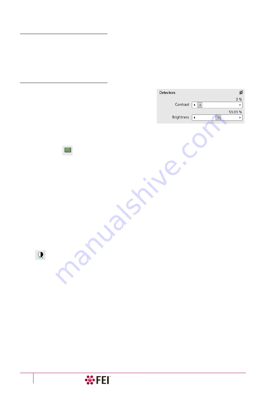
The contrast & brightness can be set manually either by adjusting
the
Detectors
module controls, using the mouse (Ctrl + click on &
dragging – horizontal / vertical direction adjusts the contrast /
brightness) or using the MUI (option):
1.
Select a medium scan speed in an active display.
2.
Reduce the contrast to zero. Adjust the brightness to a level
corresponding with the last grey level detectable by eye before
the screen goes black.
3.
Increase the contrast unless the imaging of the observed structure appears.
4.
If necessary, adjust the brightness level to improve the imaging.
Videoscope (F3)
This tool can facilitate contrast and brightness optimization to utilize full greyscale imaging range.
Three yellow horizontal lines (placed over the display) indicate white (top line), grey (middle line) and black
(bottom line) levels. The oscillogram signal amplitude / central position reflects the contrast / brightness of the
just scanned line. If the oscillogram is cut by the bottom / top line, the signal level is clipped in black / white. This
should be avoided because the imaging details are lost in the clipped areas.
Tuning the oscillogram exactly between the top and bottom lines for a feature of interest (with the use of the reduced
area) results in the full detailed imaging. The signal clipping may be used to obtain harder contrast conditions when
more black and white is needed. The signal amplitude lowering decreases the contrast, i.e. the imaging looks softer.
1.
Select a slow scan in an active display.
2.
Activate the Videoscope in an active display (F3 / clicking on toolbar icon / Scan menu) or in all live displays
(Shift + clicking on toolbar icon).
3.
Reduce the contrast to zero and adjust the brightness level to the lower dashed line (black).
4.
Increase the contrast so that the signal level just touches the upper dashed line (white).
5.
If necessary, adjust the brightness level so that the average signal level is roughly in the middle.
6.
The high and low peaks should just touch the dashed lines.
Repeating the contrast & brightness optimization helps to improve the imaging quality.
Note
Use also the following functions to optimize the Contrast / Brightness: Auto Contrast Brightness (F9), Display Saturation
(Shift + F11).
Summary of Contents for Scios 2
Page 1: ...User Operation Manual Edition 1 Mar 2017 ...
Page 103: ...Alignments I Column Alignments C O N F I D E N T I A L FEI Limited Rights Data 4 19 ...
Page 110: ...Alignments 254 GIS Alignment option C O N F I D E N T I A L FEI Limited Rights Data 4 26 ...
Page 170: ...Operating Procedures Patterning C O N F I D E N T I A L FEI Limited Rights Data 5 60 ...
Page 178: ...Maintenance Refilling Water Bottle C O N F I D E N T I A L FEI Limited Rights Data 6 8 ...


