background image


6    Installation and Setup 


Page 30 of 38 


6.2  Setup Activation 


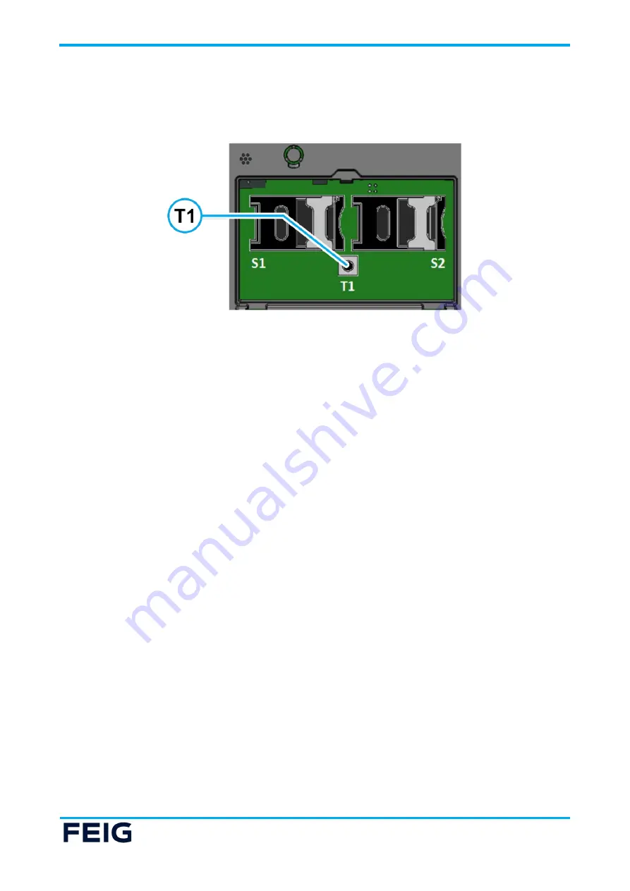
To activate the cVEND PIN setup menu the Service Mode Switch S3 (under the hinged cover) must be 
pressed. After activation please follow the display instructions. 


Fig. 24: Position of Service Mode Switch T1


Summary of Contents for cVEND PIN

Page 1: ...acher Vers No 3 19 TÜV NORD Hochfrequenztechnik GmbH Co KG LESKANPARK Gebäude 10 Waltherstr 49 51 51069 Köln Germany Tel 49 221 8888950 Annex acc to FCC Title 47 CFR Part 15 relating to FEIG ELECTRONIC GmbH cVEND PIN Annex no 5 User Manual Functional Description Title 47 Telecommunication Part 15 Radio Frequency Devices Subpart C Intentional Radiators ANSI C63 4 2014 ANSI C63 10 2013 ...

Page 2: ... Date of issue 2022 06 14 Date 2019 11 20 Created Trepper Reviewed Ftouhi Released Hittig Rademacher Vers No 3 19 TÜV NORD Hochfrequenztechnik GmbH Co KG LESKANPARK Gebäude 10 Waltherstr 49 51 51069 Köln Germany Tel 49 221 8888950 User Manual Functional Description of the test equipment EUT ...

Page 3: ...PAYMENT M90113 10e PY B INSTALLATION cVEND PIN Unattended PIN Entry Terminal with On Board Contactless Reader ...

Page 4: ... be completely avoided we are always grateful for your useful tips The instructions given in this manual are based on advantageous boundary conditions FEIG ELECTRONIC GmbH does not give any guarantee promise for perfect function in cross environments and does not give any guarantee for the functionality of the complete system which incorporates the subject of this document FEIG ELECTRONIC GmbH cal...

Page 5: ...ivacy Shield 15 5 Connectors 17 5 1 Connector X1 Power Supply and MDB Interface 17 5 2 Standby Mode Wake Up 18 5 3 Connector X2 USB Device Interface 19 5 4 Connector X3 COM 0 RS232 V 24 Interface 20 5 5 Connector X4 USB Host 2 Interface 21 5 6 Connector X5 Ethernet Interface 22 5 7 Connector X6 Auxiliary 23 5 8 Connector X7 USB Host 1 25 5 9 Connector X8 cVEND SHCR 26 5 10 Connector X9 COM 2 RS232...

Page 6: ...g 33 7 1 Cleaning 33 7 2 Battery 33 8 User Interface 34 8 1 Boot Process 34 8 2 Update Installation Indicators 34 8 3 Security Tamper 34 9 Technical Data 35 9 1 Payment Standard Compliance 36 9 2 Radio Approvals 37 9 2 1 Declaration of Conformity CE 37 9 2 2 Declaration of Conformity UKCA 37 9 2 3 Radio Approval USA FCC and Canada IC 37 ...

Page 7: ...ion of a device Repairs may only be executed by the manufacturer Installation operation and maintenance procedures should only be carried out by qualified personnel Use of the device and its installation must be in accordance with national legal requirements and local electrical codes When working on devices the valid safety regulations must be observed Special advice for carriers of cardiac pacem...

Page 8: ...ce It makes tap go and chip pin transactions easy and fast The bright color display covered by a robust and durable glass and stainless steel keys with embossed symbols in combination with illuminated keys makes cVEND PIN suitable for indoor and outdoor applications in public areas offers optimal user guidance and ensures barrier free usage For acceptance of traditional smart cards with contacts c...

Page 9: ...3 Functional Elements Page 7 of 38 3 Functional Elements Functional Elements 3 1 Front Side Fig 2 cVEND PIN front view not installed ...

Page 10: ...llation of cVEND PIN in order to enable the PIN entry function Table 1 Front side elements 3 2 Key Pad The stainless steel cVEND PIN key pad with clear tactile feedback and embossed symbols is designed for indoor and outdoor applications and provides barrier free operation The key pad function is under software control The functionality of the function keys 2 and the navigation keys 4 5 may vary d...

Page 11: ...or vending machines X2 USB Device ECR interface X3 COM Port 0 RS232 ECR interface X4 USB Host 2 Service interface for mass storage devices X5 Ethernet Host and ECR interface X6 Auxiliary Connector Digital output and audio out X7 USB Host 1 Optional fix connected GSM GPRS modem X8 cVEND SHCR Power supply and communication interface for cVEND SHCR X9 COM Port 2 RS232 Service interface ...

Page 12: ...Socket 2 S2 SAMs under application control e g public transport or other use cases Table 4 Elements under the hinged cover 4 Mechanical Integration Mechanical Integration For flush integration into a front panel the cVEND PIN has to be placed in a corresponding cutout and has to be pressed against the front plate by screwing on the four screwing points provided for this purpose For fastening threa...

Page 13: ...4 Mechanical Integration Page 11 of 38 Fig 6 cVEND PIN recommended front panel cut out ...

Page 14: ...4 Mechanical Integration Page 12 of 38 4 1 Dimensions Fig 7 cVEND PIN dimensions front view Manufacturing tolerance of cVEND PIN 82 mm x 119 9 mm 0 30 ...

Page 15: ...4 Mechanical Integration Page 13 of 38 Fig 8 cVEND PIN dimensions rear view ...

Page 16: ...4 Mechanical Integration Page 14 of 38 Fig 9 cVEND PIN dimensions side view ...

Page 17: ... the privacy shield is 270 At any horizontal angle between 315 and 45 the card holder obscures an observer s view of the PIN pad with his body a symmetrical design must meet the minimum requirements at each point The cVEND PIN Security Guidance includes more details on how the privacy shield has to be designed The angles in the figures below are defined as follows α Angle between the vertical plan...

Page 18: ...4 Mechanical Integration Page 16 of 38 ...

Page 19: ...1 2060 Plug 6 pole grid dimension 4 2 mm 2 rowed Molex Mini Fit housing Molex 39 00 0065 Crimp contact female grid dimension 4 2 mm AWG 22 28 Molex Mini Fit NOTE The Device has to be supplied by a limited power supply according EN 62368 1 Chapter Q 1 or with a NEC Class 2 LPS certified power supply Supply voltages outside the specifications may destroy the device Each Device has to be supplied by ...

Page 20: ...ing a wake up event by the cVEND and can be used by the host to activate the cVEND The host controller can awake the cVEND by pulling down the wake up line Wake up OK Key Pressing the OK key on the key pad will awake the cVEND Time controlled wake up The firmware provides functions for software programmable wake up This functionality depends on the installed application NOTE The USB connection wil...

Page 21: ... I O 4 N C 5 GND 6 Shield Table 6 Pin Assignment USB Connector X2 Required Connector The fitting complement for this connector consists of a 6 pole plug type Molex Micro Fit and the appending crimp contact Manufacturer Ordering Code Molex 43025 0600 Plug 6 pole grid dimension 3 0 mm dual row Molex Micro Fit housing Molex 43030 0001 Crimp contact female grid dimension 3 0 mm AWG 20 24 Molex Micro F...

Page 22: ...e 7 Pin Assignment RS232 V 24 Interface X3 Required Connector The fitting complement for this connector consists of a 4 pole plug type Molex Micro Fit and the appending crimp contact Manufacturer Ordering Code Molex 43025 0400 Plug 4 pole grid dimension 3 0 mm dual row Molex Micro Fit housing Molex 43030 0001 Crimp contact female grid dimension 3 0 mm AWG 20 24 Molex Micro Fit NOTE The RS232 inter...

Page 23: ... X4 a USB host interface is provided where a USB device can be connected The USB host function depends on the firmware software version Required Connector USB 2 0 type A max 500 mA NOTE The USB interface is designed for max 3 m 9 8 ft cable length Fig 14 Connector X4 USB 2 Host ...

Page 24: ...th automatic polarity correction during auto negotiation and 10 Base T signal reception CAT5 cables are recommended to ensure a reliable operation at 10 Mbps or 100 Mbps Pin Label 1 TX 2 TX 3 RX 4 VETH 5 VETH 6 RX 7 VETH 8 VETH Table 8 Pin Assignment Ethernet Connector X5 Required Connector RJ45 Fig 15 Connector X5 Ethernet Interface ...

Page 25: ...el Direction Remark 1 5 V DC O 2 External Buzzer O PWM Output max 24 V DC 100 mA 3 Opto Out C I max 24 V DC 20 mA Resistive Load 4 Opto Out E O Table 9 Pin Assignment Auxiliary Connector X6 Required Connector The fitting complement for this connector consists of a 4 pole plug type Molex Micro Fit and the appending crimp contact Manufacturer Ordering Code Molex 43645 0400 Plug 4 pole grid dimension...

Page 26: ...the external buzzer it can also be powered by an external power supply Observe the electrical parameters in Table 9 Pin Assignment Auxiliary Connector X6 Digital Output The digital output is intended to trigger external electronic inputs e g barrier control unit Fig 17 X6 AUX Schematic Fig 18 X6 Wiring External Buzzer Example Fig 19 Circuit Configuration Example ...

Page 27: ...0 Pin Assignment USB Host 1 Connector X7 Required Connector The fitting complement for this connector consists of a 5 pole plug type Molex Micro Fit and the appending crimp contact Manufacturer Ordering Code Molex 43645 0500 Plug 5 pole grid dimension 3 0 mmm single row Molex Micro Fit receptacle housing Molex 43030 0001 Crimp contact female grid dimension 3 0 mm AWG 20 24 Molex Micro Fit NOTE The...

Page 28: ...ch is the connector for Secure Hybrid Card Reader cVEND SHCR The related connection cable is included in the scope of delivery of cVEND SHCR Pin Label Direction 1 CTS 2 RxD I 3 RTS I 4 TxD O 5 GND 6 VCC SHCR O Table 11 Pin Assignment SHCR Connector X8 Fig 21 Connector X8 SHCR Connector ...

Page 29: ... RxD I 3 Device TxD O Table 12 Pin Assignment Serial Debug Port Connector X14 Required Connector The fitting complement for this connector consists of a 3 pole plug type JST PH and the appending crimp contact Manufacturer Ordering Code JST PHR 3 housing 3 pole grid dimension 2 0 mm single row JST SPH 002T P0 5 or SPH 004T P0 5 crimp contact NOTE The RS232 interface is designed for max 3 m 9 8 ft c...

Page 30: ...onnectors Page 28 of 38 5 11 SAM Sockets S1 S2 The cVEND PIN is equipped with 2 SAM sockets which are located behind the hinged cover on the back side of the device Fig 23 SAM Socket Location and Handling ...

Page 31: ...stallation are is clean and even 2 Place the cVEND PIN in the cut out 3 Screw the device tight at the four screw on points Nuts with washer are recommended 4 Check that all protection foils are removed from the key pad and the display 5 Check that the power supply complies with the specification 6 Check that all needed cables are plugged in correctly 7 Switch on the power supply and start the setu...

Page 32: ... 30 of 38 6 2 Setup Activation To activate the cVEND PIN setup menu the Service Mode Switch S3 under the hinged cover must be pressed After activation please follow the display instructions Fig 24 Position of Service Mode Switch T1 ...

Page 33: ...seven digit PINs must be configured Adding the first User ID does not require authorization if no User ID has yet been added i e for factory new devices Adding the second User ID requires the first user to authenticate via User ID and PIN As soon as two User IDs have been added the cVEND PIN will always require dual authentication for all sensitive functions It is not possible to delete a User ID ...

Page 34: ...on switches S1 S2 are pressed The same applies to the Secure Hybrid Card Reader cVEND SHCR Removal protection activation has to be carried out under dual control by two authorized users see 6 3 The activation of removal protection requires the following steps 1 Activate the cVEND PIN setup menu by pressing Service Mode switch T1 2 Enter into the removal protection activation menu by using the key ...

Page 35: ... only a damp or soft cloth for housing cleaning and prevent the usage of chemical cleaning agents Do not use chemical solvents petrol paint thinners or corrosive or abrasive substances for cleaning These can damage the surfaces and destroy the device 7 2 Battery The cVEND PIN contains a lithium battery to supply the real time clock and security circuit If the battery is discharged removed or short...

Page 36: ...ill trigger when a physical penetration attempt of the device is detected A tamper event is signalized by the cVEND PIN after power on Such a device has to be replaced Repair is only possible in the secure manufacturer environment at FEIG ELECTRONIC GmbH In case of a tamper event the buzzer periodically beeps with a frequency of 4 kHz for half a second every second On the display the message DEVIC...

Page 37: ... key and time controlled Battery1 3 V Lithium 1000 mAh lifetime 15 years at 25 C and 50 duty cycle CPU and Security ARM 9 CPU 384 MHz tamper protected and side channel attack resistant with real time memory encryption Cryptographic hardware acceleration supports SHA DES and AES True random number generator RAM MByte 128 FLASH MByte 256 Real time clock battery backed Contactless Interface ISO IEC 1...

Page 38: ... keys with from top illumination Function keys and 5 with embossments for easier operation by visually impaired persons Electrical Approvals RED 2014 53 EU BIS IS 13252 PART 1 2010 IEC 60950 1 2005 9 1 Payment Standard Compliance Payment EMV 2 6 Contactless Level 1 PCI PTS 5 x Common SECC DK Payment Kernel Level 2 Contactless MasterCard contactless VISA Paywave American Express Expresspay Discover...

Page 39: ...ference that may cause undesired operation Unauthorized modifications may void the authority granted under Federal communications Commission Rules permitting the operation of this device This equipment has been tested and found to comply with the limits for a Class A digital device pursuant to Part 15 of the FCC Rules These limits are designed to provide reasonable protection against harmful inter...

Page 40: ...in the United States with IC Radio Standards in Canada the system must be professionally installed to ensure compliance with the Part 15 certification IC certification It is the responsibility of the operator and professional installer to ensure that only certified systems are deployed in the United States Canada ...

Reviews: