IDENTIFICATION
Installation
ID ISC.ANT1520/680-A/-B
FEIG ELECTRONIC GmbH
Page 17 of 82
ID ISC.ANT1520680-A-B User
Manual_M61112-1e-ID-E-
060317.doc
5.2 Installing the antenna
5.2.1 Dimensions of antenna
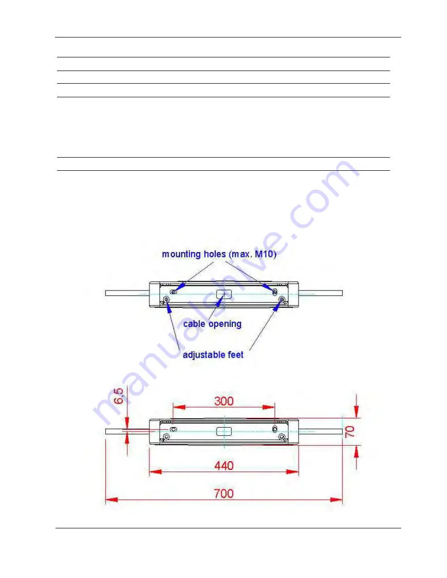
The overall dimensions of the antenna are shown in Antenna outside dimensions
Antenna outside dimensions
All dimensions are in mm with general tolerance according to ISO 2768 m (mean).
5.2.2 Drilling the Mounting Holes
If the position of the antennas has been marked or determined, the mounting holes and the holes
for the cable entry, can be marked and drilled. To make this easier the ID ISC.ANT.CRG-DT
Crystal Gate Drilling Template could be used.(optional). This Drilling template could also be used
for stabilization and weight distribution on soft grounds by mounting it additionally under the
antenna foot.The dimensions are shown in Fig. 5:
Fig. 5: Floor plate dimensions


