background image

OBID

® 

i-

scan

Application-Note

ID ISC.ANT800/600

FEIG ELECTRONIC GmbH

Page 26 of 33

N11000-2e-ID-B.doc

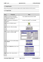
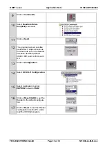
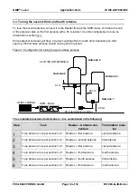
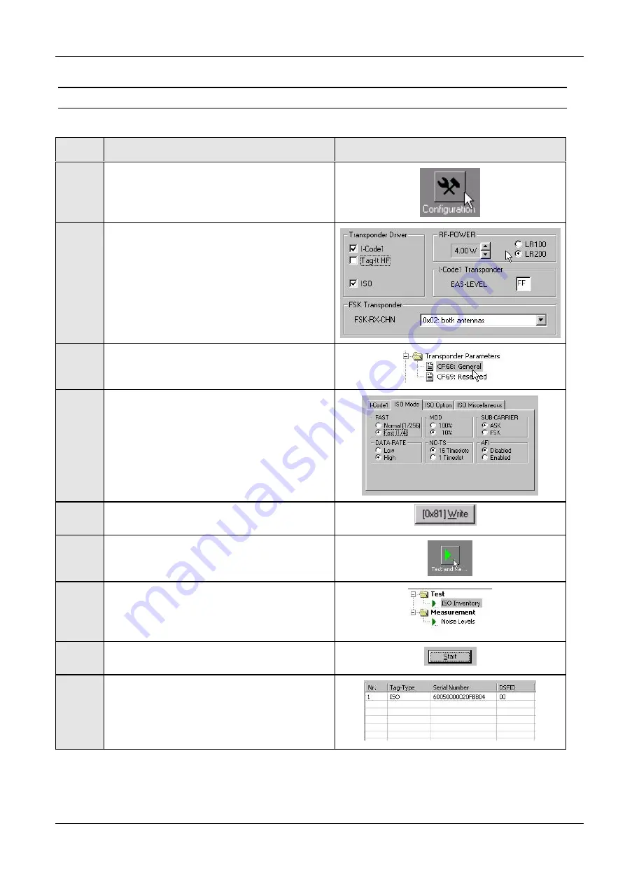
4.3. Setting the operating parameters

Step

Action

Remarks

1

Select Configuration menu

2

Configuration CFG3 RF-Interface:

Select 4 W RF power

Activate necessary transponder drivers.
Deactivate unused transponder drivers.

Set FSK-transponder, FSK-RX-CHN to

“0x02 both antennas

3

Set transponder parameters:

Configuration CFG8 General

4

Configure all used transponder types to the
desired mode

5

Set new parameters in Reader

6

Select “Test and Measurements” menu

7

Select command: “ISO Inventory“

8

Start command: “ISO Inventory“

9

If the tag is placed in the antenna field, the
serial number and tag type will be dis-
played.

Summary of Contents for ID ISC.ANT800/600

Page 1: ...ION NOTE final public 2002 06 04 N11000 2e ID B doc OBID i scan ID ISC ANT800 600 Installation and tuning of a gate antenna made from four base antennas Label reads only with parallel orientation to t...

Page 2: ...d completeness of the details given in this document and may not be held liable for damages ensuing from incorrect or incomplete information Since despite all our efforts errors may not be completely...

Page 3: ...uning the first base antenna 14 3 2 1 Tuning the base antennas 15 3 3 Tuning the second third and fourth antenna 18 3 4 Fine tuning the two antennas on the gate side 19 3 5 Measuring the standing wave...

Page 4: ...3 The gate consists of four base antennas of type ID ISC ANT800 600 A three Power Splitters type ID ISC ANT PS A and a Reader type ID ISC LR200 A The Power Splitters ID ISC ANT PS A are used to conne...

Page 5: ...than shown in the illustration The labels that are oriented parallel to the antennas can also be detected at greater distances when next to or outside the antennas Therefore no product having a label...

Page 6: ...he maximum speed of motion of the label should not exceed 0 5 1 m s this depends on the number of labels the number of data blocks the required data protocol and the label type The antenna should have...

Page 7: ...n Reader and base antenna the ID ISC ANT EC extender can be used to lengthen the antenna cable to 7 20 m 23 5 ft This will however result in a slight loss of perform ance The cable extender also requi...

Page 8: ...n of the gate all larger metallic parts must be removed from the vicinity of the antennas Figure 2 Metal free zone side view If the lower antennas are installed directly over the floor a minimum dista...

Page 9: ...magnetic field lines The result is that the label cannot be read Metal parts beneath the conveyor belt change the path of the magnetic field lines This results in significant loss of reading range Ho...

Page 10: ...of at least 50 cm 20 in from the antennas The second side mirrors side one Figure 4 Installation diagram for one gate side including cabling Two of the four base antennas are installed on one gate sid...

Page 11: ...tuning the antennas The antenna cable should always be routed vertically away from the loop at least 50 cm 20 in Also maintain a minimum distance of 50 cm 20 in from the antennas when routing other ca...

Page 12: ...ns Step Procedure Note 1 Connect the ID ISC LR200 Reader to the PC through the RS232 or RS485 port See Installation Manual ID ISC LR200 2 Install the Demo Software ISC Start Located on the OBID i scan...

Page 13: ...possible baud rates It stops as soon as the baud rate set on the Reader has been detected default 38400 8E1 and confirms with OK 13 Click on Configuration 14 Select ID ISCLR Configuration 15 Select d...

Page 14: ...the second antenna using a 50 termination resistor Begin the tuning procedure with the first base antenna Next tune the second base antenna Since the two neighboring base antennas affect each other mu...

Page 15: ...ee also section 3 5 Measuring the standing wave ratio VSWR 2 Jumpers J1 J4 and J6 8 should be checked and set as necessary Jumpers JP6 JP7 are left out Jumper JP3 must be in JP1 JP2 JP4 JP6 JP7 and JP...

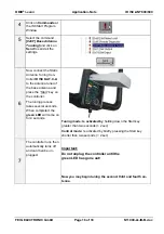
Page 16: ...se antenna and press the Start key on the controller The tuning process takes several seconds When completed the green LED will come on for 4 seconds Tuning mode Is activated by holding down the Start...

Page 17: ...ower turned off Cable between Reader and antenna defective The SMA connectors were not properly attached to the Reader or antennas or are not properly seated on the SMA sockets The cable is pinched or...

Page 18: ...or tuning the second base antenna The complete procedure for Antennas 1 4 is summarized in the following Step Task Reader Antenna con nection Termination resis tor 1 Tune Antenna 1 as per section 3 2...

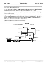
Page 19: ...be connected to terminal X1 on the Power Splitter Antenna 2 and 4 are connected to terminal X2 on the Power Splitter Figure 8 Configuration for fine tuning the first gate side Since the tuning point o...

Page 20: ...ue 3 Turn the leftmost of the two trim capacitors C2 on Antenna 2 4 approx turn counter clockwise The SWR must drop Tune the SWR to the smallest possible value 4 Turn the leftmost trim capacitor C1 on...

Page 21: ...ng no longer drops 7 Turn the right trim capacitor C1 on antenna 1 3 and Antenna 2 4 alternately slowly counter clockwise The SWR must drop Otherwise turn the trim capacitor slowly clockwise Continue...

Page 22: ...of 33 N11000 2e ID B doc Figure 9 Configuration for fine tuning the entire gate 4 x ID ISC ANT800 600 A ID ISC LR200 A 3 Power Splitters 25 cm 10 in Antenna 1 Antenna 2 Antenna 3 Antenna 4 SWR Meter...

Page 23: ...58 Lambda 2 long If the VSWR is greater than 1 3 1 after tuning use trim capacitors C1 and C2 to perform a slight adjustment Furthermore the VSWR meter can be used at any time to check the tuning of t...

Page 24: ...e ISCStart software can be found on the OBID i scan CD ROM supplied by FEIG ELECTRONIC GmbH 4 1 Reading out the serial number Step Action Remarks 1 Attach a tag to one of the antennas Adhesive tape ma...

Page 25: ...rage 400 700 mV Maximum Minimum 20 mV If the nominal values are not maintained check the following points Are all cables firmly attached and making good contact Were the toroid cores installed on the...

Page 26: ...ssary transponder drivers Deactivate unused transponder drivers Set FSK transponder FSK RX CHN to 0x02 both antennas 3 Set transponder parameters Configuration CFG8 General 4 Configure all used transp...

Page 27: ...ead range of 60 65 cm 23 5 25 5 in at should be achievable at the centre of the antenna Figure 11 Testing the antenna with a label Now slowly move the label vertical and parallel orientation to the an...

Page 28: ...detuned or defective Reader improperly configured RF power transponder type modulation transponder parame ters etc Defective cable or connector making a poor contact Reader Transformer Power Splitter...

Page 29: ...ambient conditions the antennas can be operated in the configuration as described here in EU countries using a maximum of 4 W or 1 5 W in the USA If the limit values are higher or lower the RF power m...

Page 30: ...e shielded on four sides back right left up at a distance of 50 cm to the outer edge of the antennas Shielding may consist of metal plates or wire mesh up to a mesh size of 10 cm The function of the s...

Page 31: ...ding SMA connectors female or appropriate adapters Qty 1 cable RG 58 C U approx 20 25 cm 7 8 9 8 in long with two male SMA plugs gen erally self assembled Suitable screwdriver for antenna tuning with...

Page 32: ...1 Antenna analyzer MFJ HF UHF SWR Analyzer Model MFJ 259B 1 8 170 MHz Vendors Austin Amateur Radio Supply USA 1 800 423 2604 VHT Impex Ecke Germany Tel 05224 9709 0 CIA HF Complex Impedance Analyzer 5...

Page 33: ...Inc http www tektronix de oder http www tektronix com Agilent Technoligies http www agilent com Conrad Electronic GmbH 92240 Hirschau http www conrad de ELV Elektronik AG 26787 Leer http www elv de o...

Reviews: