OBID
®
i-
scan
Application-Note
ID ISC.ANT800/600
FEIG ELECTRONIC GmbH
Page 19 of 33
N11000-2e-ID-B.doc
3.4. Fine tuning the two antennas on the gate side
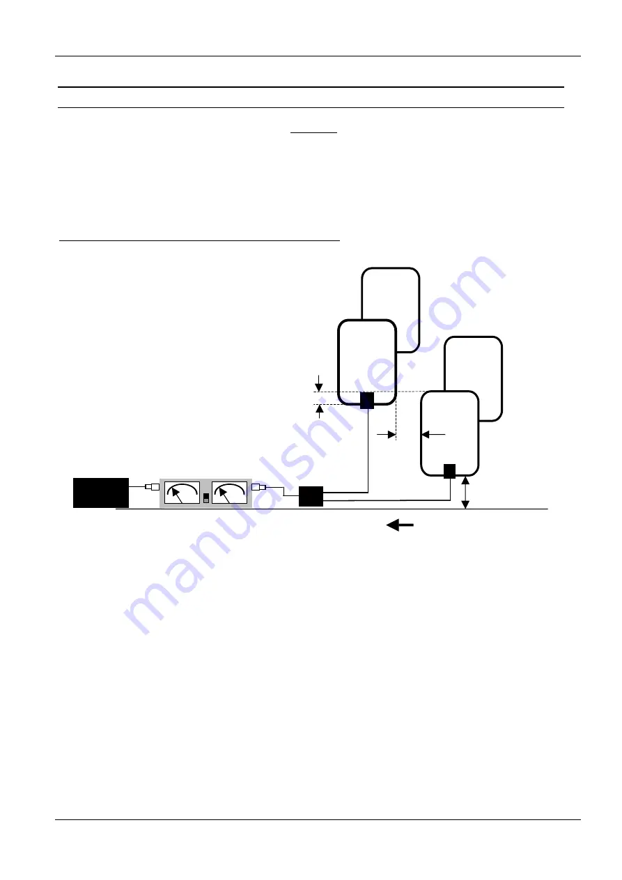
Fine tuning is performed individually for each gate side. For this the two antennas on one side
(Antenna 1 and 2 or 3 and 4) are connected with the Power Splitter and to the Reader through the
SWR meter.
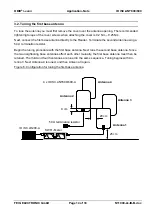
Caution! Note the current direction in the antennas
. Opposing antennas must have the same
current direction. This means Antenna 1 and 3 must be connected to terminal X1 on the Power
Splitter. Antenna 2 and 4 are connected to terminal X2 on the Power Splitter.
Figure 8: Configuration for fine tuning the first gate side
Since the tuning point of the antennas will deviate somewhat from the configuration during tuning
due to the mutual interference caused by magnetic coupling, the tuning point will need to be read-
justed slightly.
This can be accomplished with the help of an SWR meter and the four blue trim capacitors C1 and
C2 on the tuner boards.
4 x ID ISC.ANT800/600-A
ID ISC.LR200-A
Power Splitter
9 cm
20 cm
25 cm
Antenna 1
Antenna 2
Antenna 3
Antenna 4
SWR - Meter
3,6 m
(11.8 ft)
3,6 m
(11.8 ft)
20 cm
(7.9 in)
Ground
Cable lengths


