background image

OBID


i-

scan

 ® 

UHF


Installation 

ID ISC.LRU1002 


FEIG ELECTRONIC GmbH 

Page 25 of 29 

M31010-1e-ID-B.docx 


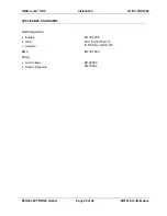
APPLICABLE STANDARDS 


Radio Regulation 

  Europe 

  USA 

  Canada 


EN 302 208 
FCC 47 CFR Part 15 
IC RSS-Gen, RSS-210 

EMC 

EN 301 489 

Safety 

  Low Voltage 

  Human Exposure 


EN 60950 
EN 50364 


Summary of Contents for ID ISC.LRU1002-FCC

Page 1: ...INSTALLATION final public B 2014 03 18 M31010 1e ID B docx ID ISC LRU1002 UHF Long Range Reader...

Page 2: ...f this document FEIG ELECTRONIC call explicit attention that devices which are subject of this document are not designed with components and testing methods for a level of reliability suitable for use...

Page 3: ...4 2 1 Power Supply via connection X2 10 4 3 Interfaces 11 4 3 1 Ethernet Interface on connector X1 11 4 3 2 USB Interface on connector X3 11 4 3 3 RS232 Interface on connector X4 12 4 3 4 Data Clock I...

Page 4: ...ical Data 23 7 Radio Approvals 26 7 1 Europe CE 26 7 2 Declaration of Conformity Directive 1999 5 EC R TTE 27 7 3 USA FCC and Canada IC 28 7 3 1 USA FCC and Canada IC warning notices 28 7 3 2 Label In...

Page 5: ...valid for the device The manufacturer shall not be held legally responsible for inaccuracies errors or omissions in the manual or automatically set parameters for a device or for an incorrect applicat...

Page 6: ...and 2 Watts This allows read ranges of up to 8m 2 2 Available Reader types The following Readers are available Table 1 Available Reader Types Reader type Description ID ISC LRU1002 EU Device version...

Page 7: ...ID B docx 3 Installation The Reader is designed for wall mount including outdoors Holes for mounting on a wall are provided in the housing It is not necessary to open the reader housing for mounting 2...

Page 8: ...n for the different cables are used Table 4 Push button function shows the available push buttons Figure 2 Connection Overview Table 3 Connection terminals Connector Description ANT 1 4 Connection of...

Page 9: ...nectors are positioned on the lower side of the reader The maximum tightening torque for the SMA sockets is 0 45 Nm 4 0 lbf in CAUTION Exceeding the tightening torque will destroy the plug Table 5 Ext...

Page 10: ...Pin Assignment Table 6 Pin assignment for power supply Terminal Abbreviation Description X2 Pin 1 VDC Vcc supply voltage 24 V DC 5 X2 Pin 2 GND Ground supply voltage CAUTION The reader has to be suppl...

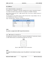
Page 11: ...P protocol is that each device has a unique address on the net work All Readers have a factory set IP address Table 7 Standard factory configuration of the Ethernet connection Network Address IP Adres...

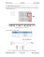
Page 12: ...S232 interface is connected on X4 The transmission parameters can be configured by means of software protocol Figure 6 RS232 interface pin outs on X4 Table 8 Pin Assignment RS232 Interface Pin Number...

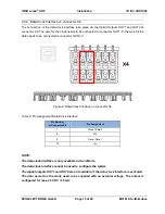
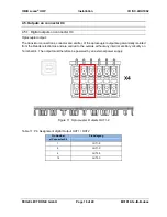
Page 13: ...be connected to connector OUT2 C Figure 8 Data Clock Interface on connector X4 Table 9 Pin Assignment Data Clock Interface Pin Number at Connector X4 Pin Assignment 7 Clock Data 0 8 Vcc 9 Data Data 1...

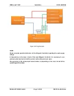
Page 14: ...e limitations of the Wiegand Controller regarding the used supply voltage In dependency on the inner circuit of the used Wiegand Controller it is necessary to use external serial resistors to limit th...

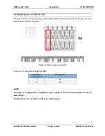
Page 15: ...lly isolated from the Reader electronics and must therefore be externally supplied Figure 10 Optocoupler pin outs IN1 Table 10 Pin Assignment digital Input IN1 Pin Number at Connector X4 Pin Assignmen...

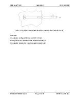
Page 16: ...llector and emitter of the optocoupler output are galvanically isolated from the Reader electronics and are carried to the outside without any internal ancillary circuitry on Terminal X4 The output mu...

Page 17: ...9 M31010 1e ID B docx Figure 12 Internal and possible external wiring of the optocoupler outputs OUT1 2 CAUTION The output is configured for max 24 V DC 30 mA Polarity reversal or overload on the outp...

Page 18: ...t Relay Output REL1 CAUTION The relay output is configured for max 24 V DC 2 A constant load The switching current must not exceed 1A The relay output is intended for switching resistive loads only If...

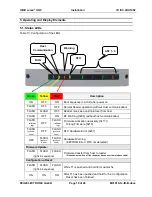
Page 19: ...ASH alternat ing OFF FLASH alternat ing Firmware Activation necessary 0x17 Wrong Firmware 0x18 FLASH synchro nous OFF FLASH synchro nous RFC Hardware Error 0xF1 OFF FLASH synchro nous FLASH synchro no...

Page 20: ...ton T1 a complete configuration reset can be a reset you should use a paper clip and push the button T1 for at least 5 s until left side are switched on continuously see 5 1 Status LEDs Table 13 Confi...

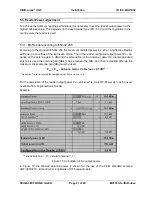
Page 21: ...configured output power Pout de pends on the antenna gain in dBi and the attenuation of the antenna cable If a circular polarized antenna is used the antenna gain dBic can be reduced by 3dB At a linea...

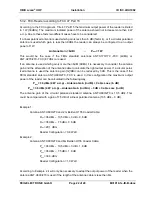
Page 22: ...the right output power If a circular polar ized antenna is used the antenna gain G dBic can be reduced by 3dB This is the case if the FEIG standard antenna ANT U600 270 FCC is used In this configurat...

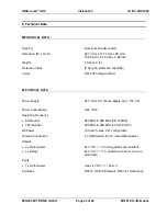
Page 23: ...RAL 9003 Signal White ELECTRICAL DATA Power Supply 24 V DC 5 Noise Ripple max 150 mV Power Consumption max 18 W Operating Frequency EU Reader FCC Reader 865 MHz to 868 MHz EN 302208 902 MHz to 928 MHz...

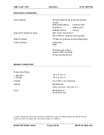
Page 24: ...ptical Indicators 16 LEDs for operating status and diagnostics Further Features Anticollision RSSI RF Channel monitoring Antenna SWR monitoring Temperature Monitoring AMBIENT CONDITIONS Temperature Ra...

Page 25: ...LRU1002 FEIG ELECTRONIC GmbH Page 25 of 29 M31010 1e ID B docx APPLICABLE STANDARDS Radio Regulation Europe USA Canada EN 302 208 FCC 47 CFR Part 15 IC RSS Gen RSS 210 EMC EN 301 489 Safety Low Volta...

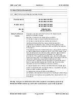
Page 26: ...10 1e ID B docx 7 Radio Approvals 7 1 Europe CE When properly used this radio equipment conforms to the essential requirements of Article 3 and the other relevant provisions of the R TTE Directive 199...

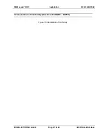
Page 27: ...OBID i scan UHF Installation ID ISC LRU1002 FEIG ELECTRONIC GmbH Page 27 of 29 M31010 1e ID B docx 7 2 Declaration of Conformity Directive 1999 5 EC R TTE Figure 18 Declaration of Conformity...

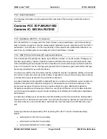
Page 28: ...o Part 15 of the FCC Rules These limits are designed to provide reasonable protection against harmful interference when the equipment is operated in a commercial environment This equipment generates u...

Page 29: ...d for that type are strictly prohibited for use with this device The antennas used for this transmitter must be installed to provide a separation distance of at least 23 cm from all persons and must n...

Reviews: