


Identification
Manual
ID ISC.MR102
FEIG ELECTRONIC GmbH
Page 26 of 153
H01113-4e-ID-B.docx
TRANS-FORM
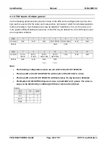
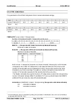
3
:
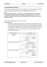
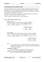
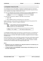
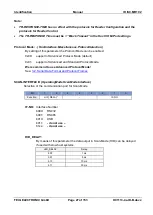
By means of this byte, several parameters for the data transmission format of the asyn-
chronous interface can be defined.
Bit:
7
6
5
4
3
2
1
0
Function:
0
0
0
0
S
D
P
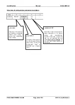
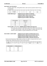
P:
(HostInterface.Serial.Parity)
Kind of Parity
b00:
no Parity
b01:
even Parity
b10:
odd Parity
b11:
- do not use -
D:
(HostInterface.Serial.Databits)
Number of Data Bits
b0:
8 Data Bits
b1:
- do not use -
S:
…
(
HostInterface.Serial.Stopbits)
Number of Stop Bits
b0:
1 Stop Bit
b1:
- do not use
–
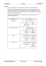
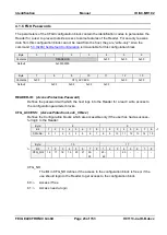
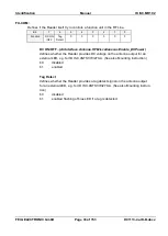
Note:
Changing of TRANS-FORM only becomes effective after writing / saving configu-
ration block CFG1 to EEPROM and reset of the Reader.
Always 8 Data Bits and 1 Stop Bits should be used
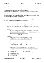
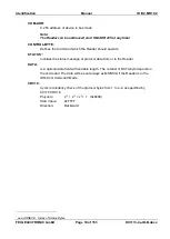
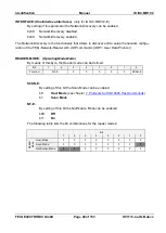
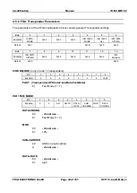
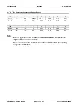
TR-RESPONSE-TIME:
(AirInterface.TimeLimit)
By means of this parameter the maximum duration for the Transponder command can be de-
fined.
The TR-RESPONSE-TIME starts after the Reader has received a new command. At the
latest after the TR-RESPONSE-TIME elapsed the Reader will send an answer protocol. In
this case, the current commands between Reader and Transponder are aborted. If this
time i
s too short the Interface Status “ 0x83 RF Communication Error“ will appear.
max. response duration
TR-RESPONSE-TIME
0...65535 * 5 ms
3
A reasonableness check is performed by writing this parameter to the Reader. If an error occurs the Read-
er answers with STATUS = 0x11.


