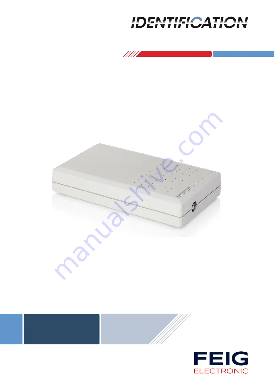
background image


INSTALLATION MANUAL


 final 

– public (B) 

2018-01-18 

– M01210-6e-ID.doc


ID ISC.MR102 

For all variants 


Summary of Contents for ID ISC.MR102

Page 1: ...INSTALLATION MANUAL final public B 2018 01 18 M01210 6e ID doc ID ISC MR102 For all variants...

Page 2: ...forts errors may not be completely avoided we are always grateful for your useful tips The instructions given in this manual are based on advantageous boundary conditions FEIG ELECTRONIC GmbH does not...

Page 3: ...Wiring 7 Housing versions 7 Dimensions 7 Module version 8 Dimensions 8 Connections 9 Antenna terminal ANT 1 10 DC Voltage supply on antenna connector ANT1 10 Power supply 11 Power supply via X1 11 Po...

Page 4: ...mbH Page 4 of 26 M01210 6e ID doc Technical Data 16 Radio Approvals 18 Europe CE 18 Europe CE 19 USA FCC and Canada IC 20 UL Approval USA and Canada 22 Annex 23 Accessories 23 Wall mounting kit ID ISC...

Page 5: ...ically set parameters for a device or for an incorrect application of a device Repairs may only be undertaken by the manufacturer Installation operation and maintenance procedures should only be carri...

Page 6: ...reading of up to 100 ISO15693 or ISO18000 3M3 transponders per second The Reader electronics is contained in a plastic housing having an IP30 enclosure rating Available Reader types The following rea...

Page 7: ...be wall mounted in this case the wall mount kit should be ordered separately see Appendix Wall mounting kit ID ISC MS MR PR A Notes The distance between two readers of the same type should not fall be...

Page 8: ...ounting in other equipment Notes The distance between two readers of the same type should not fall below 4m Before any installation the intended position of the reader should be tested for it s suit a...

Page 9: ...rrangement and the Table 2 Connectors shows which connector can be used for the different interface cable X2 X4 X1 X1 X3 ID ISC MR102 PoE ID ISC MR102 USB ANT 1 ID ISC MR102 ID ISC MR102 A Figure 3 Co...

Page 10: ...The optimum operating Q factor of the antenna should be in a range of QB 10 20 To determine the operating Q the antenna must be supplied with a 50 Ohm source such as a network analyzer or frequency g...

Page 11: ...The unit has to supplied by a listed NEC Class 2 LPS Power supply only Power supply recommendations To take full advantage of the Reader performance you must use a sufficiently regulated and low noise...

Page 12: ...le Figure 4 LAN and PoE connection Note It must be ensured that the reader is supplied with 42 5 V DC 48 V DC cable losses at least The maximum cable distance for Ethernet is 100m A connection of the...

Page 13: ...9 pin D Subminiature female connector See also Connections X2 Interface Power supply 2 TxD 3 RxD 5 GND 7 GND 9 Vcc 1 4 6 8 n c Table 7 Connection assignment of the connector X2 For this reader a seri...

Page 14: ...a factory set IP address Interface parameter can be configured via soft ware protocol e g ISOStart Network Address IP Address 192 168 10 10 Subnet Mask 255 255 255 0 Port 10001 DHCP OFF Table 9 Stand...

Page 15: ...Table 10 shows the default setting Abbreviation Description LED green RUN Turns on when the Reader is ready LED red LABEL Turns on when a transponder is detected Flashes if a RF Warning appears red g...

Page 16: ...rical Data Supply voltage ID ISC MR102 A B USB ID ISC MR102 PoE 12 24V DC 12 24V DC or PoE Power consumption max 9 W Operating frequency 13 56 MHz Transmitting power 1 2 W 1 dB Antenna connection SMA...

Page 17: ...M3 Upgrade Code required Address setting for interface Software 0 254 Addresses Visual indicators 1 LED multicolor red green Ambient Conditions Temperature range Operation Storage 25 C to 55 C 13 F to...

Page 18: ...TRONIC GmbH declares that the radio equipment type ID CPR74 is in com pliance with Directive 2014 53 EU The full text of the EU declaration of conformity is available at the following internet address...

Page 19: ...Identification Installation ID ISC MR102 FEIG ELECTRONIC GmbH Page 19 of 26 M01210 6e ID doc Europe CE...

Page 20: ...f the FCC Rules These limits are designed to provide reasonable protection against harmful interference when the equipment is operated in a commercial environment This equipment generates uses and can...

Page 21: ...essionally installed to ensure compliance with the Part 15 certification IC certification It is the responsibility of the operator and professional installer to en sure that only certified systems are...

Page 22: ...MR102 FEIG ELECTRONIC GmbH Page 22 of 26 M01210 6e ID doc UL Approval USA and Canada The following UL label position is on the back side of the reader ID ISC MR102 A ID ISC MRM102 A ID ISC MR102 PoE...

Page 23: ...data cable with integrated supply voltage line 1686 000 00 ID CAB USB A USB cable 2 5m 1687 000 00 ID CO RS232 485 External RS232 RS485 converter 1663 000 00 ID ISC ANT340 240 A External antenna Dime...

Page 24: ...S MR PR A The wall mounting kit can be used to attach the Reader to a flat surface Remove the screws from the back side of the Reader Attach the individual wall hangers using the screws supplied with...

Page 25: ...MR102 FEIG ELECTRONIC GmbH Page 25 of 26 M01210 6e ID doc Serial data cable ID CAB RS A PC D Sub 9pol female DC Jack 2 5 x 5 5mm GND outside Vcc inside Reader D Sub 9pol male Figure 8 Serial data cab...

Page 26: ...ication Installation ID ISC MR102 FEIG ELECTRONIC GmbH Page 26 of 26 M01210 6e ID doc Antenna Figure 9 ID ISC ANT340 240 Figure 10 ID ISC ANT310 310 Figure 11 ID ISC ANTS370 270 Figure 12 ID ISC ANTH2...

Reviews: