IDENTIFICATION
ID LR(M)5400
Installation and mounting
Installation
Page 17 of 30
Jumper settings power supply
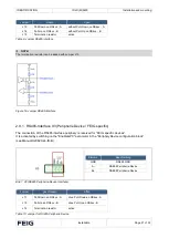
Digit. Eingänge
Jumper
Beschreibung
IN1 (X2)
J1
Bypassing the series resistor at VDC < 10 V
IN2 (X2)
J3
Bypassing the series resistor at VDC < 10 V
IN3 (X2)
J5
Bypassing the series resistor at VDC < 10 V
Table 4: Jumper for inputs IN1, IN2 und IN3
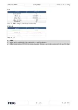
Setting internal or external power supply
Power supply
Jumper: J2, J4, J6
External power supply (U
external
)
open
Internal VDC power supply U
internal
)
closed
Table 5: Select power supply
external series resistances for external power supply
Power supply
Jumper: J1, J3, J5
5 VDC
– 10 VDC
IN
10 VDC
– 24 VDC
OFF
Table 6: Settings external power supply
NOTE:
•
The internal 24 VDC voltage for supplying the DC voltage on the digital inputs is not protected by the fuse F1.
•
The simultaneous use of an internal and an external power supply is not permitted.


