OBID
®
classic-pro
Manual
ID CPR30.xx
FEIG ELECTRONIC GmbH
Page 52 of 126
H01114-0e-ID-B.docx
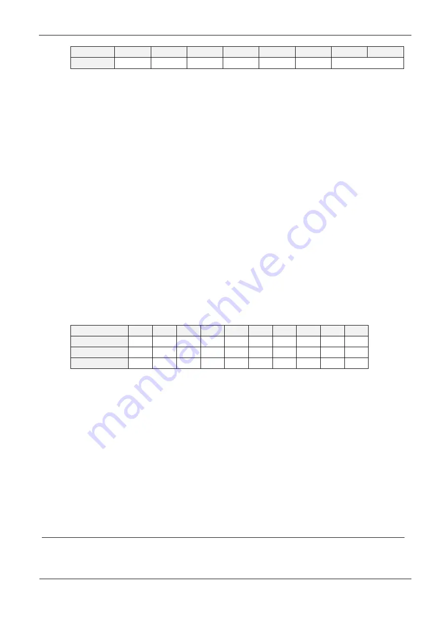
Bit:
7
6
5
4
3
2
1
0
Function
-
-
-
-
-
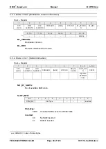
L4_SLCT
C_LEVEL
C_LEVEL:
This 2 bits displays the Cascade Level of the Transponder UID
b00:
Cascade Level 1 (4 byte UID)
b01:
Cascade Level 2 (7 byte UID)
b10:
Cascade Level 3 (10 byte UID)
L4_SLCT:
This bit displays the select status of the present Transponder.
b0:
The Transponder is not selected in ISO14443-4 level.
b1:
The Transponder is selected on ISO14443-4 level by the reader now. A
further select command is not necessary for data exchange with this
Transponder.
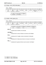
UID:
ISO 14443A UID could have different lengths. This depends on the Cascade Level of the
Transponder (see also TR_INFO byte). It is transmitted by the reader with a length of 7 or
10 byte.
The following table shows the structure of the UID in relation to ISO14443-3
transmitted byte
9
10
11
12
13
14
15
16
17
18
Cascade-Level 1
0
0
0
UID3 UID2 UID1 UID0
-
-
-
Cascade-Level 2 UID6 UID5 UID4 UID3 UID2 UID1 UID0
(*
-
-
-
Cascade-Level 3 UID9 UID8 UID7 UID6 UID5 UID4 UID3 UID2 UID1 UID0
(*
* UID0: Manufacturer ID according ISO/IEC7816-6/AM1
In case of a shorter UID the redundant bytes are filled with 0 at the most significant digits.
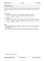
NOTICE:
The UID byte order can be swapped by using the parameter CFG3.ISO14443
FTUR.UID_ORDER
1
In case of NXP mifare chips this byte also indicates the chip type. Further information's are given in the NXP
Application Note "mifare Interface Platform, Type Identification Procedure" M018412.


