background image

OBID i-

scan

®

Montage

ID ISC.MR100-A / PR100-A

FEIG ELECTRONIC GmbH

Seite 17 von 39

M10202-3de-ID-B.doc

D E U 

T

 S C

 H

Summary of Contents for OBID i-scan ID ISC.MR100-A

Page 1: ...MONTAGE INSTALLATION final public B 2003 08 20 M10202 3de ID B doc OBID i scan ID ISC MR100 A ID ISC PR100 A deutsch english ...

Page 2: ...OBID i scan Montage ID ISC MR100 A PR100 A FEIG ELECTRONIC GmbH Seite 2 von 39 M10202 3de ID B doc D E U T S C H deutsche Version ab Seite 3 english version from page 22 E N G L I S H ...

Page 3: ... für die Richtigkeit und Vollständigkeit der An gaben in diesem Dokument Insbesondere kann FEIG ELECTRONIC GmbH nicht für Folgeschäden auf Grund fehlerhafter oder unvollständiger Angaben haftbar gemacht werden Da sich Fehler trotz aller Bemü hungen nie vollständig vermeiden lassen sind wir für Hinweise jederzeit dankbar Die in diesem Dokument gemachten Installationsempfehlungen gehen von günstigst...

Page 4: ...chluss X2 7 3 2 Versorgungsspannung 8 3 3 Antennenanschluss X4 nur ID ISC MR100 9 3 4 Asynchrone Schnittstelle 10 3 4 1 Schnittstellenkonfiguration mittels Jumper 10 3 4 2 RS232 Schnittstelle 11 3 4 3 RS485 Schnittstelle 12 3 4 4 Adresseinstellung für Busbetrieb 12 4 Bedien und Anzeigeelemente 13 4 1 LED 13 5 Technische Daten 14 6 Zulassungen 16 6 1 USA FCC 16 6 2 Europa CE 16 7 Anhang 18 7 1 Zube...

Page 5: ...ss der Haftung und der Hersteller übernimmt keine Gewährleistung Für das Gerät gelten die Gewährleistungsbestimmungen des Herstellers in der zum Zeitpunkt des Kaufs gültigen Fassung Für eine ungeeignete falsche manuelle oder automatische Ein stellung von Parametern für ein Gerät bzw ungeeignete Verwendung eines Gerätes wird kei ne Haftung übernommen Reparaturen dürfen nur vom Hersteller durchgefüh...

Page 6: ...ader verfügt über eine interne Antenne so dass keine externe Antenne benötigt wird Eine Anticollision Funktion ermöglicht das gleichzeitige Lesen von mehreren Transpondern Die Elektronik des Readers ist in einem Kunststoffgehäuse untergebracht welches die Schutzart IP30 besitzt Der Reader verfügt über eine asynchrone Schnittstelle die wahlweise als RS232 oder RS485 konfiguriert werden kann Durch d...

Page 7: ... Tauglich keit geprüft werden Nur ID ISC PR100 Das Gerät darf nicht direkt auf leitende Materialien wie Metallflächen Metallgitter Ar mierung oder metallisierte Oberflächen montiert werden da diese Flächen eine Redu zierung der Lesereichweite bewirken Der Abstand zu derartigen Flächen sollte min destens 10 cm betragen 3 1 Spannungs und Schnittstellenanschluss X2 Zum Anschluss der Spannungsversorgu...

Page 8: ...urzzeichen Beschreibung X2 Pin 9 12V 12 V DC Versorgungsspannung X2 Pin 7 AGND Ground Versorgungsspannung Tabelle 4 Anschluss der Versorgungsspannung Netzteilempfehlungen Zur Ausnutzung der vollständigen Leistungsfähigkeit des Reader Moduls sollte auf eine ausrei chend stabilisierte und rauschfreie Spannungsversorgung geachtet werden Bevorzugt wird ein lineares Netzteil mit 12V DC 580 mA Bei der V...

Page 9: ...güte muss die Antenne mit einer 50Ω Ω Ω Ω Quelle z B einem Network Ana lyzer oder einem Frequenzgenerator versorgt werden Beim Anschluss einer Antenne ist darauf zu achten dass diese die zulässigen Grenz werte der nationalen Vorschriften bezüglich Funkanlagen nicht überschreitet Installation mit FCC Zulassung In Länden in denen eine FCC Zulassung benötigt wird darf der Reader nur mit den in Tabell...

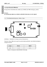
Page 10: ...eis Der gleichzeitige Betrieb von RS232 und RS485 Schnittstelle ist nicht möglich 3 4 1 Schnittstellenkonfiguration mittels Jumper Abbildung 1 Leiterplatte mit Jumpern und Anschlusssteckern Über den Jumper J21 kann die asynchrone Schnittstelle als RS232 oder RS485 Schnittstelle konfiguriert werden Jumper RS232 RS485 J21 1 2 2 3 Tabelle 8 Konfiguration RS232 RS485 Schnittstelle J74 J73 J21 J72 J23 ...

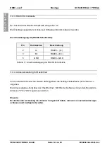
Page 11: ...ohne Pull Down an RS485 A J77 Abschlusswiderstand RS485 A RS485 B ohne Abschlusswiderstand RS485 A RS485 B Tabelle 9 Konfiguration RS485 Schnittstelle J73 J77 J74 RS485 B RS485 A Abbildung 2 Jumper der RS485 Schnittstelle 3 4 2 RS232 Schnittstelle Der Anschluss der RS232 Schnittstelle erfolgt über X2 Die Übertragungsparameter können per Softwareprotokoll konfiguriert werden Anschlussbelegung X2 RS...

Page 12: ...rzzeichen Beschreibung 2 A RS485 A 3 B RS485 B 5 GND RS485 GND Tabelle 11 Anschlussbelegung der RS485 Schnittstelle 3 4 4 Adresseinstellung für Busbetrieb Für den Busbetrieb bietet der Reader die Möglichkeit die benötigte Busadresse per Software zu vergeben Die Adressvergabe erfolgt über den Host Rechner Mit Hilfe der Software können dem Reader die Adressen 0 bis 254 zugewiesen werden Hinweis Da a...

Page 13: ...n per Software konfiguriert werden Kurzzeichen Beschreibung LED grün RUN Signalisiert den ordnungsgemäßen Ablauf der internen Reader Software Leuchtet wenn der Reader betriebsbereit ist LED rot LABEL Leuchtet wenn ein Transponder erkannt wird LED orange INITIALISIERUNG Blinkt während der Reader Initialisierung nach dem Ein schalten Tabelle 12 Standard Konfiguration der LED ...

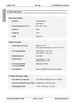
Page 14: ...rgung typisch 12 V DC max Spannungsbereich 12 24 V DC 15 Leistungsaufnahme ID ISC MR100 max 8 VA ID ISC PR100 max 5 VA Betriebsfrequenz 13 56 MHz Sendeleistung ID ISC MR100 1 0 W ID ISC PR100 0 5 W Antennenanschluss nur ID ISC MR100 SMA Buchse 50Ω Schnittstellen RS232 und RS485 wahlweise einstellbar Funktionelle Eigenschaften Unterstützte Transponder ISO 15693 kompatibel I Code 1 Tag it HF Adresse...

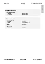
Page 15: ...IC GmbH Seite 15 von 39 M10202 3de ID B doc D E U T S C H Umgebungsbedingungen Temperaturbereich Betrieb Lagerung 25 C bis 60 C 25 C bis 70 C Angewendete Normen Zulassung Funk Europa USA EN 300 330 FCC 47 CFR Part 15 EMV EN 300 683 Sicherheit Europa EN 60950 ...

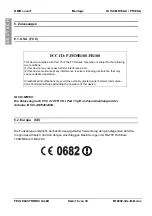
Page 16: ...ny interference received including interference that may cause undesired operation Unauthorized modifications may void the authority granted under Federal communica tions Commission Rules permitting the operation of this device ID ISC MR100 Die Zulassung nach FCC 47 CFR CH I Part 15 gilt im Zusammenhang mit der Antenne ID ISC ANT340 240A 6 2 Europa CE Die Funkanlage entspricht bei bestimmungsgemäß...

Page 17: ...OBID i scan Montage ID ISC MR100 A PR100 A FEIG ELECTRONIC GmbH Seite 17 von 39 M10202 3de ID B doc D E U T S C H ...

Page 18: ...DC Netzteil mit passendem Stecker für ID CAB RS A 1690 000 00 ID CAB RS A Serielles Datenkabel mit integrierter Ver sorgungsleitung 1691 000 00 ID ISC MS MR PR A Wandmontagesatz für ID ISC MR100 und ID ISC PR100 1687 000 00 ID CO RS232 485 Externer RS232 RS485 Umsetzer 1663 000 00 ID ISC ANT340 240 Externe Antenne Abm 340mm x 240mm x 9mm Schutzart IP30 1451 000 00 ID ISC ANT300 300 Externe Antenne...

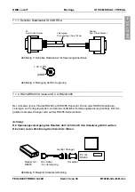
Page 19: ...onverter Wenn zwei RS232 Handshake Leitungen zur Verfügung stehen wird keine zusätzliche Versorgungsspannung benötigt Der mit gelieferte Gender Changer wird auf der RS485 Seite montiert Achtung Die Spannungsversorgung des Readers darf nicht durch den Umsetzer geführt werden Dies kann zu der Zerstörung des Umsetzers führen Abbildung 5 Beispiel Umsetzerschaltung PC 9 pol D Sub Buchse Reader 9pol D S...

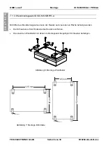
Page 20: ...ID ISC MS MR PR A Mit Hilfe des Wandmontagesatzes kann der Reader auf einer ebenen Fläche befestigt werden Die Schrauben auf der Rückseite des Readers entfernen Die einzelnen Wandhalter mit denen im Montagesatz beigefügten Schrauben befestigen Abbildung 6 Montage Wandhalter 3mm 3mm 152 mm 65 mm 92 mm 125 mm Abbildung 7 Montage Bohrmaße ...

Page 21: ...OBID i scan Montage ID ISC MR100 A PR100 A FEIG ELECTRONIC GmbH Seite 21 von 39 M10202 3de ID B doc D E U T S C H ...

Page 22: ...e FEIG ELECTRONIC GmbH does not guarantee the correctness and completeness of the details given in this manual and may not be held liable for damages ensuing from incorrect or incomplete information Since despite all our efforts errors may not be completely avoided we are always grateful for your useful tips The installation instructions given in this manual are based on advantageous boundary cond...

Page 23: ...nal X2 26 9 4 Supply voltage 27 9 5 Antenna terminal X4 only ID ISC MR100 28 9 6 Asynchronous interface 29 9 6 1 Interface configuration using jumpers 29 9 6 2 RS232 interface 30 9 6 3 RS485 interface 31 9 6 4 Setting the address for bus mode 31 10 Control and Display Elements 32 10 1 LED 32 11 Technical Data 33 12 Approvels 35 12 1 USA FCC 35 12 2 Europe CE 35 13 Appendix 37 13 1 Accessories 37 1...

Page 24: ...unauthorized measures shall exclude any liability by the manufacturer The liability prescriptions of the manufacturer in the issue valid at the time of purchase are valid for the device The manufacturer shall not be held legally responsible for inaccuracies errors or omissions in the manual or automatically set parameters for a device or for an incorrect application of a device Repairs may only be...

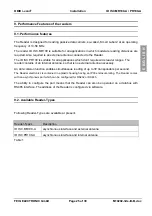
Page 25: ... ranges The reader contains of an internal antenna so that is no external antenna necessary An anti collision function enables simultaneous reading of up to 30 transponders per second The Reader electronics is contained in a plastic housing having an IP30 enclosure rating The Reader comes with an asynchronous port which can be configured for RS232 or RS485 The ability to configure the port means t...

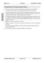
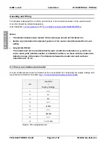
Page 26: ...sition of the reader should be tested for ist suit ability Only ID ISC PR100 The reader must not be installed directly upon conductive materials as e g metal sur faces metal grids reinforcements or metallized surfaces as these surfaces reduce the detection range of the reader The distance between the reader and such surfaces should be min 10 cm 9 3 Power and interface terminal X2 A 9 pin D sub fem...

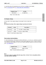
Page 27: ...roy the device Terminal Name Description X2 Pin 9 12V 12 V DC supply voltage X2 Pin 7 AGND Ground supply voltage Table 4 Connecting the supply voltage Power supply recommendations To take full advantage of the Reader module performance you must use a sufficiently regulated and noise free power supply Preferred is a linear power supply with 12V DC 580 mA When us ing a switching power supply be sure...

Page 28: ... 10 20 To determine the operating Q the antenna must be supplied with a 50 Ohm source such as a network analyzer or frequency generator When connecting an antenna ensure that it does not exceed the permissible limits pre scribed by the national regulations for radio frequency devices Installation with FCC Approval In countries where FCC approval is required the ID ISC MR100 Reader may only be oper...

Page 29: ...gured as either RS232 or RS485 Note It is not possible to run both RS232 and RS485 at the same time 9 6 1 Interface configuration using jumpers Fig 1 Circuit board with jumpers and sockets Jumper J21 is used to configure the asynchronous interface as RS232 or RS485 Jumper RS232 RS485 J21 1 2 2 3 Table 8 Configuring as RS232 RS485 J74 J73 J21 J72 J23 J24 1 X2 X4 1 2 3 4 5 6 7 8 9 J77 ...

Page 30: ...ll Down on RS485 A out Pull Down on RS485 A J77 Termination resistor RS485 A RS485 B no termination resistor RS485 A RS485 B Table 9 Configuring the RS485 interface J73 J77 J74 RS485 B RS485 A Fig 2 Jumper of the RS485 interface 9 6 2 RS232 interface The RS232 interface is connected through X2 The transmission parameters can be configured using software protocol Pin assignments X2 RS232 interface ...

Page 31: ... X2 RS485 interface Pin Abbrev Description 2 A RS485 A 3 B RS485 B 5 GND RS485 GND Table 11 Wiring assignments for the RS485 interface 9 6 4 Setting the address for bus mode For bus operation the Reader can be assigned a bus address using software Addresses are assigned by the host computer Using the software addresses 0 to 254 can be assigned to the Reader Note Since all Readers are factory set w...

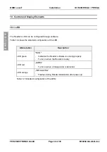
Page 32: ...be configured through software Table 12 shows the standard configuration of the LED Abbreviation Description LED green RUN Indicates the Reader software is running properly Turns on when the Reader is ready LED red LABEL Turns on when a transponder is detected LED orange INITIALIZING Flashes during Reader initialization after power up Table 12 Standard configuration of the LEDs ...

Page 33: ...ply voltage typical 12 V DC max voltage range 12 24 V DC 15 Power consumption ID ISC MR100 max 8 VA ID ISC PR100 max 5 VA Operating frequency 13 56 MHz Transmitting power ID ISC MR100 1 0 W ID ISC PR100 0 5 W Antenna connection only ID ISC MR100 SMA female 50Ω Interfaces RS232 and RS485 configurable Functional properties Supported transponders ISO 15693 compatible I Code 1 Tag it HF Address settin...

Page 34: ...ELECTRONIC GmbH Page 34 of 39 M10202 3de ID B doc E N G L I S H Ambient conditions Temperature range Operation Storage 25 C to 60 C 25 C to 70 C Applicable Norms Radio approval Europe USA EN 300 330 FCC 47 CFR Part 15 EMC EN 300 683 Safety Europe EN 60950 ...

Page 35: ...ust accept any interference received including interference that may cause undesired operation Unauthorized modifications may void the authority granted under Federal communica tions Commission Rules permitting the operation of this device ID ISC MR100 Approval per FCC 47 CFR CH I Part 15 applies to use with the antenna ID ISC ANT340 240 12 2 Europe CE When used according to regulation this radio ...

Page 36: ...OBID i scan Installation ID ISC MR100 A PR100 A FEIG ELECTRONIC GmbH Page 36 of 39 M10202 3de ID B doc E N G L I S H ...

Page 37: ...ith suitable con nector for ID CAB RS A 1690 000 00 ID CAB RS A Serial data cable with integrated supply voltage line 1691 000 00 ID ISC MS MR PR A Wall mounting kit for ID ISC MR100 and ID ISC PR100 1687 000 00 ID CO RS232 485 External RS232 RS485 converter 1663 000 00 ID ISC ANT340 240 External antenna Dimensions 340mm x 240mm x 9mm Enclosure rating IP30 1451 000 00 ID ISC ANT300 300 External an...

Page 38: ... channel RS232 to RS485 converter No external power is required if two RS232 output handshake lines are available The supplied gender changer is installed on the RS485 side Note The supply voltage for the Reader is not permitted to be brought through the converter This could destroy the converter Fig 5 Example converter circuit PC 9 pin D sub female Reader 9 pin D sub male Supply DC adapter 2 5mm ...

Page 39: ...mounting kit ID ISC MS MR PR A The wall mount kit can be used to attach the Reader to a flat surface Remove the screws from the back side of the Reader Attach the individual wall hangers using the screws supplied with the mounting kit Fig 6 Mounting wall hangers 3mm 3mm 152 mm 65 mm 92 mm 125 mm Fig 7 Mounting drill dimensioning ...

Reviews: