OBID i-
scan
®
Installation
ID ISC.MR100-A / PR100-A
FEIG ELECTRONIC GmbH
Page 28 of 39
M10202-3de-ID-B.doc
E N
G
L I S H
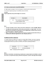
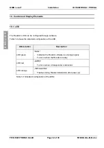
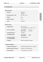
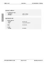
9.5. Antenna terminal X4 (only ID ISC.MR100)
An SMA socket is provided on the circuit board for connecting the external antenna.
The maximum tightening torque for the SMA socket is 0.45 Nm.
Caution:
Higher tightening torque will damage the connector.
Terminal
Description
X4
Connecting the external antenna
(input impedance 50
Ω
)
Table 6: Connecting the external antenna
Note:
•
The input impedance for the antenna should be calibrated to a value of 50
Ω
Ω
Ω
Ω
±±±±
(3
Ω
Ω
Ω
Ω
∠
∠
∠
∠
3°).
•
The optimum operating Q factor of the antenna should be in a range of QB = 10...20. To
determine the operating Q the antenna must be supplied with a 50 Ohm source such as
a network analyzer or frequency generator.
•
When connecting an antenna, ensure that it does not exceed the permissible limits pre-
scribed by the national regulations for radio frequency devices.
Installation with FCC Approval:
In countries where FCC approval is required, the ID ISC.MR100 Reader may only be operated
using the antennas listed in Table 7. Changes or modifications not expressly authorized by the
relevant approval body may result in revocation of the user’s operating permission.
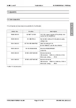
Article No.
Part No.
1663.000.00
ID ISC.ANT340/240
Table 7: Antennas with FCC Approval
Note:
Electrical connection, commissioning, maintenance, measurement and calibration work on
the unit is to be performed only by electrical specialists or persons with equivalent training.

