background image


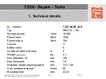
FEIN - Repair - Tools


Alle Rechte bei FEIN, insbesondere für den Fall der Schutzrechtanmeldung.  
Jede Verfügungsbefugnis wie Kopieren und Weitergabe liegt bei FEIN. 

MVK 

04 / 08 

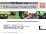
4.2. Remove flange and wheel guard 

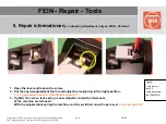
1.  Remove flange from the drive shaft with a  pulling off device 
2.  Remove securing ring - 

Attention:

 ring is pre loaded - 

Risk of injury 

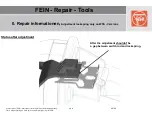
3.  Remove securing ring, spring plate, notching ring, spring and wheel guard 
4.  

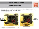
!!! Attention new  wheel guard with stop, new safety rules !!! 
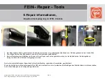
  

Tools: 
 

- pulling off device 
- spring-ring  plier 
   outer ring , straight 

Summary of Contents for WSS14-125

Page 1: ...FEIN Repair Tools Alle Rechte bei FEIN insbesondere für den Fall der Schutzrechtanmeldung Jede Verfügungsbefugnis wie Kopieren und Weitergabe liegt bei FEIN MVK 04 08 WS 14 125 ...

Page 2: ...fügungsbefugnis wie Kopieren und Weitergabe liegt bei FEIN MVK 04 08 Contents 0 Important informations 1 Technical Details 2 Maintenance 3 Function control 4 Disassembly 5 Assembly 6 Tools 7 Special information Drawings Spare part lists please see in the internet www fein de FEIN Service Spare parts ...

Page 3: ...ld coil unit For improvement of durability of our tools a technical change on the air conducting ring was made As shown in the right picture some additional reinforcements were put on the housing to increase the stability in general and as a prevention against breakage of the air conducting ring Since production date 06 2009 only reinforced air conducting rings will be used Old New ...

Page 4: ...Schutzrechtanmeldung Jede Verfügungsbefugnis wie Kopieren und Weitergabe liegt bei FEIN MVK 04 08 0 Repair information Difference field coil unit WS 14 Screw retainer RED Field coil unit with rubber bush WS 13 EVO Screw retainer WHITE Field coil unit without rubber bush ...

Page 5: ...sions the power cables are assembled with core cable ends The crimping of the core cable ends must be done as a trapeze crimping to guarantee a safety and durable clamping It s recommended esspecially on 110 V and 120 V machines to use the preassembled original cables Even on 220 V machines a cable with core cable ends can be used as described before but it s not necessary 8 1 mm 220 V Version 110...

Page 6: ...20 V versions By connecting the cable core ends into the clamp please watch necessarily for the correct position see picture Otherwise the clamp will be damaged and the cable gets loose If this happen the function of the machine is not warranted The correct fixing can be checked by pulling the cable slightly A pushing down of the white buttons are very helpful for the connection of the cable insid...

Page 7: ... MVK 04 08 0 Repair informationen Lock spring adjustment only on WSS Versions With change of the gear case or the field coil unit the lockspring must be adjusted in every case to adjust the tolerances of the separate components The correct adjustment of the lockspring guarantees the switch interlock with opened lever Delivery status Status after adjustment ...

Page 8: ...Verfügungsbefugnis wie Kopieren und Weitergabe liegt bei FEIN MVK 04 08 0 Repair informationen Lockspring adjustment only on WSS Versions Delivery status In the delivery status a gap always exists between switch rod and lockspring With installation an adjustment is always necessary see next page ...

Page 9: ...WSS Versions 1 Open the lever and loosen the screw 2 Put the special adjustment tool in and adjust the lockspring in the right position no gap between switch rod and lockspring 3 Tighten the screw lock spring is now adjusted and all the tolerances of the machine are removed With the adjusted lockspring the machine can t be switched on with open lever Lock on switch Tools screw driver torx 20 adjus...

Page 10: ... der Schutzrechtanmeldung Jede Verfügungsbefugnis wie Kopieren und Weitergabe liegt bei FEIN MVK 04 08 0 Repair informationen Adjustment lockspring only on WSS Versions Status after adjustment After the adjustment shouldn t be a gap between switch rod and lockspring ...

Page 11: ...d 2 Die richtige Position des Spannhebels wird durch die Haltefeder gewährleistet 3 Bei der Einstellung der Haltefeder muß diese mit dem Finger nach unten gedrückt werden bis die Haltefeder am Getriebegehäuse anliegt Jetzt kann die Schraube festgezogen werden Nur bei korrekt schließendem Spannhebel ist die Schaltfunktion speziell das Ausschalten gewährleistet Wenn die Haltefeder nicht korrekt eing...

Page 12: ...halter Pos 70 kommen Der Grund dafür resultiert aus einer Lageveränderung der Polpaketeinheit im Motorgehäuse Verantwortlich dafür ist eine Beschädigung Bruch der Polpaketeinheit im Bereich des Luftleitringes siehe Bilder unten roter Kreis Um solche Ausfälle zu vermeiden ist im Reparaturfall bei älteren Maschinen eine Sichtkontrolle auf derartige Beschädigungen unbedingt durchzuführen und ggf Polp...

Page 13: ...04 08 1 Technical details Id number 7 221 40 00 23 0 Typ WSS 14 125 No load speed 1 min 10 000 Power input Watt 1200 Power output Watt 750 Current 1 Safety class II Length of cable with plug m 4 Weight without cable kg 2 1 Disc diameter Ø mm 125 Disc thickness mm 1 6 Diameter elastic backing pad Ø mm 115 125 max peripheral speed m sec 80 Mounting hole mm 22 23 ...

Page 14: ... serious operational hazards for the user BGV A3 Carry out all routine tests in accordance with DIN VDE 0702 After repairs observe the regulations according to DIN VDE 0701 Part 1 Only use original FEIN replacement parts At initial operation observe the relevant accident prevention regulations of the trade and professional associations For information on intended use in Germany refer to the produc...

Page 15: ...den Fall der Schutzrechtanmeldung Jede Verfügungsbefugnis wie Kopieren und Weitergabe liegt bei FEIN MVK 04 08 3 Electrical function control 3 1 Short function control 3 2 Major function control 1 3 3 Major function control 2 3 4 Wiring plan 3 5 Safety test ...

Page 16: ...gsbefugnis wie Kopieren und Weitergabe liegt bei FEIN MVK 04 08 3 1 Short function control 3 1 1 Check of the interlock Plug in the grinder in switch on mode Grinder shouldn t run otherwise electronic defect Switch the grinder off and on again Grinder must run again 3 1 2 Check no load speed 10 000 U min ...

Page 17: ... of the motor switch self start lock is activated Carbon brushes are worn out Motor defective Electronics defective Switch motor switch off and on again Test continuity Check Clean area Visual inspection measurement Check motor without electronics Loosen motor connections from electronics Operate motor using transformer with max 75 mains voltage Check electronics without motor Loosen motor connect...

Page 18: ...the initiation of the self start lock for example Electronics defective Test continuity See above 3 2 3 Speed varies Machine too weak regular behaviour not noticeable Electronics defective Additional mechanical loading drive bearing vibrations collector carbon brushes defective Electronics defective See above Check Visual check of brush sparking Measure motor voltage Voltage must rise when the mac...

Page 19: ...te bei FEIN insbesondere für den Fall der Schutzrechtanmeldung Jede Verfügungsbefugnis wie Kopieren und Weitergabe liegt bei FEIN MVK 04 08 3 4 Wiring plan 65 Cable protection hose 70 Switch 260 Power cable X2 X3 Plug connection ...

Page 20: ...act time min 3 Sec meas pt Armature Protective insulation through shaft insulation Insulation test Ins resistance 2 0 MOhm Contact time min 3 Sec meas pt Sequence of the safety test 1 15 min test run no load 2 Switch test when lever 480 not closed the switch 110 can not be switched on 3 Voltage return test 4 Insulation test Contact gear housing 135 5 High voltage test Gear housing 135 5 motor hous...

Page 21: ...embly 4 1 Preparation 4 2 Remove flange and wheel guard 4 3 Remove motorhousing and power cabel 4 4 Bearing plate gear housing brush holder 4 5 Disconnect armature field coil unit 4 6 Dismount armature 4 7 Dismount switch rod electronic 4 8 Dismount electronic 4 9 Dismount switch 4 10 Disassembly switch lever unit 4 11 Disassembly armature 4 12 Drive shaft 4 13 Gear housing ...

Page 22: ...er Schutzrechtanmeldung Jede Verfügungsbefugnis wie Kopieren und Weitergabe liegt bei FEIN MVK 04 08 4 1 Preparation 1 Disconnect the tool from the mains 2 Set switch Off position 3 Open the clamping lever and remove the clamping unit Take off the inserted accessories ...

Page 23: ... 04 08 4 2 Remove flange and wheel guard 1 Remove flange from the drive shaft with a pulling off device 2 Remove securing ring Attention ring is pre loaded Risk of injury 3 Remove securing ring spring plate notching ring spring and wheel guard 4 Attention new wheel guard with stop new safety rules Tools pulling off device spring ring plier outer ring straight ...

Page 24: ...ergabe liegt bei FEIN MVK 04 08 4 3 Remove motorhousing and power cable Tools screwdriver torx 20 screwdriver slotted for disconnect power cable 1 Unscrew the srews 5x on the motor housing 2 Remove top cover 3 Remove strain relief 2 screws and lower part housing 4 Disconnect power cabel from the connecting clamp by using a screw driver ...

Page 25: ...aring plate gear housing brush holder Tools screwdriver torx 20 flat plier 1 Unscrew 4 screws on the gear cover and remove them 2 Take off the gear cover remove the grease if necessary 3 Unscrew 4 screws on the gear housing Attention different screw lenght 4 Remove the dust protection on the brush holder on the top 5 Pull out both brush holder including the carbon brushes ...

Page 26: ...unit Tools screwdriver slotted cable hook 1 Remove gear housing with armature from the field coil unit by 2 screw driver please make sure that the brush holder incl The carbon brushes are pulled out completly Risk of breakage during pulling off the armature 2 Pull off the aramture from the field coil unit if the rubber ring will stack in the field coil unit pull it out from the unit with a cable h...

Page 27: ...ll der Schutzrechtanmeldung Jede Verfügungsbefugnis wie Kopieren und Weitergabe liegt bei FEIN MVK 04 08 4 6 Dismount armature Tools plastic hammer 1 Clamping the armature with gear housing in a vice pull off the gear housing by slightly hits with a plastic hammer ...

Page 28: ...ll der Schutzrechtanmeldung Jede Verfügungsbefugnis wie Kopieren und Weitergabe liegt bei FEIN MVK 04 08 4 7 Dismount switch rod electronic Tools wire clip 1 Pushing out the plastic cover in front 2 Remove the plastic cover 3 Unlock the electronic with a wire clip ...

Page 29: ...eren und Weitergabe liegt bei FEIN MVK 04 08 4 8 Dismount electronic Tools flat plier 1 Bend up the switch rod slightly and remove it completly with the switch rod unit Atention Risk of breakage 2 Disconnect the plugs on the electronic and pull the electronic off 3 Pull off the brushholder with a flat plier from the cable ...

Page 30: ... FEIN MVK 04 08 4 9 Dismount switch Tools flat plier 1 Unscrew the screws on top of the switch 2 Pull off the switch carefully from the bracket Attention different material on the brackets 1 x plastic 1 x metal risk of breakage on the plastic one Please use only switches with the piece of rubber inside additional dust protection and electrical safety ...

Page 31: ...anmeldung Jede Verfügungsbefugnis wie Kopieren und Weitergabe liegt bei FEIN MVK 04 08 4 10 Disassembly switch lever unit 1 Pull out the sliding switch with a slotted screwdriver 2 Push the switch rod back as far as possible and take it out from the cover Tools screwdriver slotted ...

Page 32: ...08 4 11 Disassembly armature 1 Put the armature into the tube with the pulling off device and press the pinion down with a punch drift 2 Press down the magnet ring with a pulling off device and a 3 9 mm punch drift 3 Change the ball bearings if necessary Tools press tube 64101002004 D 120mm pulling off device 64102069007 pulling off device 64102072000 punch drift ...

Page 33: ...ndle with ball bearing cover plate and gear from the plate 2 Put the spindle with the ball bearing onto a bush and press the spindle out of the ball bearing and the gear 3 If necessary press down the pressure plate in the spindle with a 6 mm punch drift Attention preloaded spring package take out the securing ring with a slotted screwdriver Put the spring package on a punch drift or a wire to prev...

Page 34: ... device onto the gear housing and clamp it in a vice 2 Push out the bolt with a 4 5 mm punch drift 3 If necessary push out the bushes with a 6 5 mm punch drift 4 Take out the lever the bolt and the eccentric ring 5 If necessary you can drive out the needle bearing with slightly hammer hits after warming up the gear housing Tools hammer 200g punch drift D 4 9mm punch drift D 6 9mm mounting device 6...

Page 35: ...K 04 08 5 Assembly 5 1 Armature 5 2 Gear housing 5 3 Assembling clamping lever 5 4 Armature Gearhousing 5 5 Assemble switch 5 6 Preassembling switch rod 5 7 Preassembling field coil unit 5 8 Armature Field coil unit 5 9 Drive shaft 5 10 Cover plate 5 11 Brush holder Carbon brushes 5 12 Motorhousing 5 13 Wheel guard 5 14 Lockspring adjustment see under point 7 ...

Page 36: ...n device 2 Put on the cover plate ball bearing and the ball bearing support plate press on the ball bearing 3 Put in the ball bearing in to the support plate and press it on 4 Warm up the pinion approx 100 C and press it on 5 Press on the magnet ring with the base plate as distance holder support Werkzeuge forceps o Ä hot air gun support plate inner Ø 7 1 mm support plate inner Ø 8 3 mm mandrel pr...

Page 37: ...i FEIN MVK 04 08 5 2 Gear housing WSS 14 1 Put in the gearhousing to the pressing in device 2 Lay in the thrust washer and the spring washer to the gearhousing 3 Press in the needle bearing to the gear housing Please make sure that the labelled site of the needle bearing is shown to the pressure pin Werkzeuge press in device 64114024005 mandrel press ...

Page 38: ...s wie Kopieren und Weitergabe liegt bei FEIN MVK 04 08 5 2 Gear housing WSG 14 1 Put in the locking oin to the gear housing 2 Lay in the pressure spring 3 Put on the cover to the locking pin and push it on as long as the cover snap in Please fix the locking pin by backpressure or mounting on the cover plate first ...

Page 39: ...14 1 Screw on the mounting device to the gear housing and put in the pressure pin 2 Clamp in the mounting device together with the gear housing to a vice 3 Mount on the clamping lever with the excentric ring and the bolt in closed position Lubricate the excentric ring with Molykote Paste D slightly Drive in the bolt with a hammer and a punch Tools Mounting device 64122020006 Hammer 200g Punch D 4 ...

Page 40: ...htanmeldung Jede Verfügungsbefugnis wie Kopieren und Weitergabe liegt bei FEIN MVK 04 08 5 4 Armature Gear housing WSS WSG 14 1 Clamp the preassembled armature into a vice 2 Put on the gear housing to the armature and assemble it by slightly hammer hits Tools Vice Plastic hammer ...

Page 41: ... WSS WSG 14 1 Loosening the screws on top of the switch 2 Move on the switch carefully to the retaining plate 3 Tighten the screws with approx 0 5 Nm Attention two different materials on the retaining plates 1 x plastic 1 x metal risk of breakage on the plastic one Please use only switches with a rubber plug additional dust protection und electrical safety Werkzeuge Schraubdreher PH 2 ...

Page 42: ...sbesondere für den Fall der Schutzrechtanmeldung Jede Verfügungsbefugnis wie Kopieren und Weitergabe liegt bei FEIN MVK 04 08 5 6 Preassembling switch rod WSS 14 1 Put in the switch to the lever insert 2 Put in the switch lever and push it in ...

Page 43: ...sbesondere für den Fall der Schutzrechtanmeldung Jede Verfügungsbefugnis wie Kopieren und Weitergabe liegt bei FEIN MVK 04 08 5 6 Preassembling switch rod WSG 14 1 Put in the switch to the lever insert 2 Put in the switch lever and push it in ...

Page 44: ...n the switch rod with the lever insert to the electronic 2 Slide in the electronic with the lever insert to the mechanical feed on the field coil unit as long as the electronic snap in 3 Put the cover in and snap it in Attention don t forget it safety issue Not on WSG 14 4 Connect the cables brown on to the electronic connect the blue cables together and move over the cable protective tube Tools C...

Page 45: ... Armature Field coil unit WSS WSG 14 1 Move the armature with gear housing into the field coil unit Put the rubber bush on to the ball bearing before move in Clamping lever in closed position 2 Screw on the gear housing on to the field coil unit Please pay attention on the different screw length Tools Screw driver torx 20 Screw short 13 mm length Screw long 20 mm length ...

Page 46: ...Drive shaft WSS 14 1 Put in the spring package thrust piece and pressure plate to the driving shaft Pay attention on the lamination of the spring washer 2 Press the spring package together under a mandrel press and put the circlip in 3 Press on the ball bearing to the driving shaft 4 Press on the cover plate and the gear to the driving shaft Tools Punch 6mm Mandrel press ...

Page 47: ...bei FEIN MVK 04 08 5 9 Drive shaft WSG 14 1 Press on the ball bearing to the drive shaft 2 Lay down the gear and the cover plate on a bush and press in the preassembled drive shaft 3 Press in the preassembled drive shaft to the plate Please pay attention on the right position of the cover plate short end long end Werkzeug Durchschlag 6mm Dornpresse ...

Page 48: ...reassembled drive shaft in to the plate 2 Put the preassembled plate in to the gear housing and screw it on 3 Check the face clearance it might be adjusted with shims 4 Take off the plate and fill in 20g of grease 0 40 101 01000 4 Needle bearing has to be slightly lubricated not filled up with grease 5 Put the plate on again and screw it on Tools Bush D 20 5 Screwdriver torx 20 Grease 0 4010101000...

Page 49: ...rush holder with the carbon brushes in to the field coil unit and connect it Attention brush holder are different pay attention on the cable connection don t make a loop and put the copper wires in to the existing cable channel otherwise the cable could be jammed and function of the switch rod could be blocked 2 Put the brush cover piece of rubber on to the top holder on the switch lever side Tool...

Page 50: ...Kopieren und Weitergabe liegt bei FEIN MVK 04 08 5 12 Motor housing WSS WSG 14 1 Put the preassembled motor in to the underpart of the motor housing 2 Screw the cord grip on 3 Bring the wiring into the line and put the upper part of the motor housing on 4 Screw the motor housing together Tools screw driver torx 20 1 2 ...

Page 51: ... 13 Wheel guard WSS WSG 14 1 Lay on the spring lever safety guard spring washer 2 Adjust the circlip with a circlip plier 3 Press the circlip with a bush down till the circlip snap in Watch for the right size of the circlip the spring washer might be adjusted Attention new wheel guard with a stop because of new safety rules Tools bush 28mm circlip plier mandrel press ...

Page 52: ...chte bei FEIN insbesondere für den Fall der Schutzrechtanmeldung Jede Verfügungsbefugnis wie Kopieren und Weitergabe liegt bei FEIN MVK 04 08 6 Tools 6 1 Tools 6 2 Special tools 6 3 Typ of grease quantity 6 4 Adhesives Sealants ...

Page 53: ...l press 2t Retail Vice Retail Punch Ø 4 5 mm Retail Punch Ø 6 5 mm Retail Plastic hammer Retail Steel hammer Retail Screwdriver PH 2 Retail inner circlip plier Retail outer circlip plier Retail Pulling off device KUKKO 43 1 Retail Hot air gun Retail Forceps Retail Bush ID 24 5mm AD 40mm H 60mm Bush ID 20 5mm AD 30mm H 60mm Bush ID 30 5mm AD 30mm H 60mm Tube ID 54mm AD 59 5mm H 65mm ...

Page 54: ...e hook 0 72 00 310 066 Tube Ø120 mm 6 41 01 002 004 Plate 6 41 02 069 007 Pulling off bell 6 41 04 150 008 Clamping sleeve Ø 19 mm 6 41 07 019 007 Clamping sleeve Ø 26 mm 6 41 07 026 000 Pressing on device 6 41 01 019 008 Pressing in device 6 41 14 024 005 Assembly Disassembly device 6 41 22 020 006 Adjusting tool Lock spring 6 41 08 003 010 Two part base plate Magnetring 6 41 02 072 000 ...

Page 55: ...180 C Temperature range 30 C to 120 C Normally loaded spur gear and roller bearing also slide bearing with higher speed 85g tube 3 21 600 0301 4 800g tin 3 21 320 070 1 4500g tin 3 21 320 1001 5 Gears 430 20g 0 40 106 0100 1 old Sst6 Drop point approx 190 C Temperature range 60 C to 130 C Roller bearing grease Highest speed roller bearings Neutral against E and NE metals and resistant plastics PA ...

Page 56: ...ion Colour Contents Description Position quantity 09000600401 Loctite 222 old 221 Purple 50 ml Screw retainer through thread screw retainer low strength For securing and sealing threaded joints safe against vibrations easty to disassemble best gap 0 05 mm max 0 12 mm for threads M16 fine thread M36 55C to 150C hand tight 15 30 min final tightness 3h storage time min 12 months For all types of plas...

Page 57: ...rechtanmeldung Jede Verfügungsbefugnis wie Kopieren und Weitergabe liegt bei FEIN MVK 04 08 The left picture shows an armature which strips on the field coil unit no damage on ball bearings This occurs a local heating on the field coil unit right picture 7 Special information ...

Page 58: ...liegt bei FEIN MVK 04 08 The incorrect adjustment of the field coil unit is the reason for the stripping of the armature It can be checked by a visual inspection Through an incorrect assembling the edge guide is might be broken left picture Thereby occurs an air gap between the edge guide and the field coil right picture 7 Special information ...

Page 59: ...iegt bei FEIN MVK 04 08 If the field coil unit is correct assembled there is no air gap between the edge guide and the field coil The field coil must touch the plastic cover and has to be tighten If this is the reason for a machine failure the field coil unit has to be changed at all hazards A new adjustment is impossible 7 Special information ...

Reviews: