


FeiYu Tech
Guilin Feiyu Electronic co.,Ltd http://www.feiyu-tech.com Email:feiyudz@yahoo.cn
5
then glow steady. If some of the led
’
s do not light , inspect all your weld points. You can also take a
volt meter and on DC range, check for proper voltage Aprox. 2.3vdc is present at the weld points.
Once you have the led
’
s inspected, remove the battery, place the fuselage you removed previously and
place eight button head screws in the corresponding holes and tighten them.
The Magic cable tie use for fi
xed battery.
The frame Power detection support 3S (11.1V )battery. Connect a 3S Lipo Balance plug to the plug on
the bottom of the Fuselage.
Power detection:
Fuselage Led flash.
Status
LED on
Slow flash
Medium flash
Fast flash
battery
>11.5V
11.1V~11.5V
10.8V~11.1V
<10.8V
note
Enough power
Voltage
reduction
Need landing
Landing
immediately
Step 4: Installing the ESC
’
s and the Battery connector.
Take the six esc
’
s out of their package, This is an important step to be observed. On five of the esc
’
s,
remove the
“
Red
”
positive lead from the servo connector. Place a small piece of Shrink tubing over
the wire as not to cause a short.
This is done as the FY91Q and the Compass module needs only one power source..
Connect the three blue wires with the female connectors to the motor leads. As for now you don
’
t
need to worry about direction the motor is turning.
Do this for all six motors and esc
’
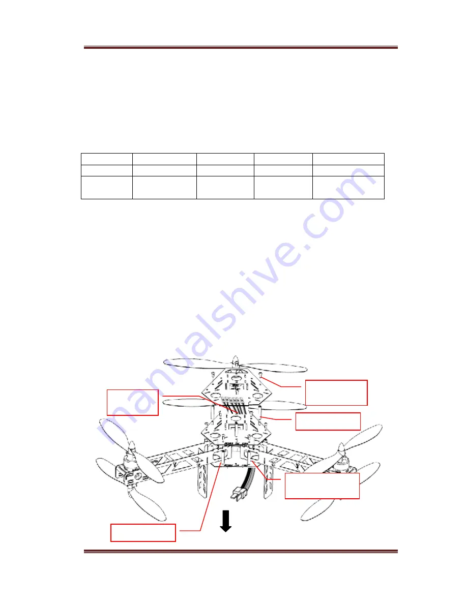
s. Running the wires between the pillars and the sides of the frames,
poke the servo connectors up through the top Fuselage plate at each point corresponding to each motor.
Run each JST Battery male plug through the same hole as the servo lead.
Insert the male plugs from the Battery plug assembly as indicated on the photo, attach each Female
JST to each of the plugs.
M3
×
30mm Pillar
M3
×
5mm
Scoket Screw
Front
M3
×
25mm Pillar
Power cable through
Round hole
6 ESCs wire
through out


