27
"
#
!
!
#
#
!
"
Bandsaw
FB 540/640/740/840/940
7.4.3 Setting the saw blade guides
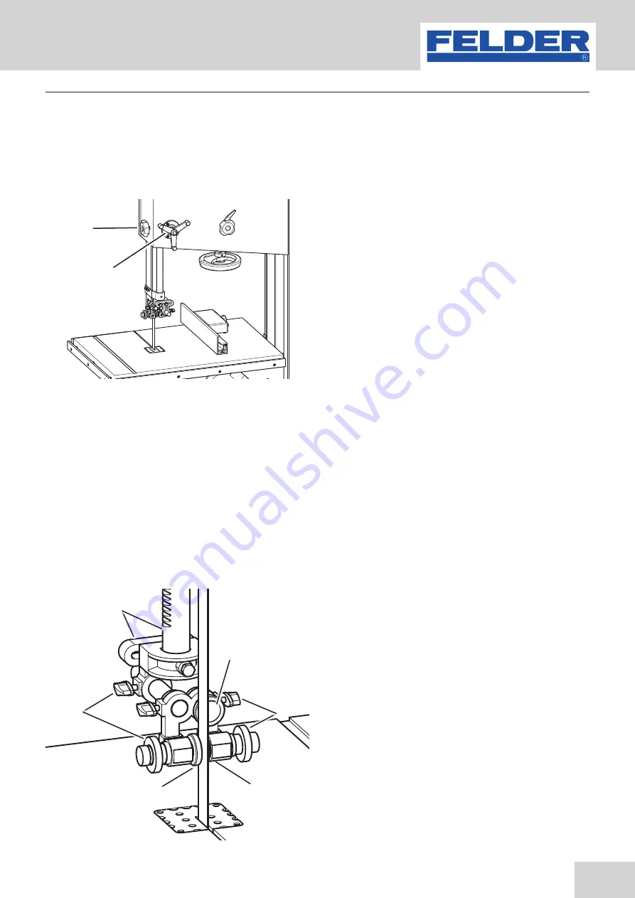
The upper saw belt guide has to be lowered as closely
as possible to the workpiece (5-10 mm).
To set the height, open the clamping screw and turn
the handwheel until the desired height is achieved and
clamp the clamping screw again tightly.
This adjustment may not be executed whilst the machine
is in operation!
The side guide rollers should graze the saw belt slightly
to ensure a vibration-free and straight cut. The position
of these rollers can be adjusted with the adjusting screws
and then clamped with the locking ring. The guide rollers
should be positioned approx. 2 mm behind the saw belt
teeth.
The rear support roller prevents strong pushing back of
the saw blade during the cut and should be clamped 1-2
mm behind the band saw blade after opening the clam-
ping screw.
Fig. 20: Bearings
Fig. 21: Saw blade guide
7.4.3.1 Height adjustable protection device
!
Clamping screws
"
Blade guide height adjustment
7.4.3.2 Saw blade guide upper/down
• If the lower saw belt guide is also a ball bearing mo-
del, the same installation instructions are applicable
as for the upper saw belt guide.
• The fixed saw belt guide is comprised of a base
with 2 screwed in wooden pads. The wooden pads
should graze the saw belt slightly to guarantee a
vibration-free and straight cut.
!
Bearings
"
Support roller
#
Clamping screws
Operation
Summary of Contents for FB 540
Page 5: ...5 Bandsaw FB 540 640 740 840 940 Table of Contents...
Page 40: ...40 Bandsaw FB 540 640 740 840 940 11 Spare parts Spare parts...
Page 41: ...41 Bandsaw FB 540 640 740 840 940 Spare parts...
Page 42: ...42 Bandsaw FB 540 640 740 840 940 Spare parts...
Page 43: ...43 Bandsaw FB 540 640 740 840 940 Spare parts...
Page 44: ...44 Bandsaw FB 540 640 740 840 940 Spare parts...


