background image

03

04

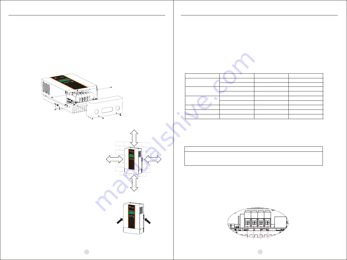
Install the unit to the wall by screwing two screws.
Refer to right chart.

Overcurrent Protection and Disconnects

CAUTION: 

Circuit breakers or fuses must be installed in both battery and solar


circuits.

The battery circuit breaker or fuse must be rated to 125% of the maximum current or more. The recommended 
breaker/fuse rating for use with the charger is listed in the below table.

Recommended breaker rating:

Minimum battery circuit breaker/fuse rating

1.25 x 30Amps  = 37.5 Amps                1.25 x 45Amps  = 56.3 Amps
1.25 x 60Amps  = 75.0 Amps                1.25 x 80Amps  = 100.0 Amps
1.25*100Amps  = 125Amps                  1.25*120Amps  = 150Amps

A disconnect is required for the battery and solar circuits to provide a means for removing power from 
the charger. Double pole switches or breakers are convenient for disconnecting both solar and battery 
conductors simultaneously.

Connect the Power Wires

The solar modules can produce open-circuit voltages in excess of 100 Vdc when in sunlight. Verify if solar 
input breaker or disconnect has been opened (disconnected)before connecting system wires.

WARNING: Shock Hazard

3. INSTALLATION

3.3 Mounting the Unit

3.2 Preparation

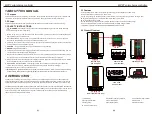
Before installation, please inspect the unit. Be sure that nothing inside the package is
damaged. You should have received the following items inside of package:
      •Solar charge controller x 1
      •User manual x 1

Before connecting all wirings, please take off wiring box cover by removing screws as
shown below.

3.1 Unpacking and Inspection

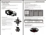
Consider the following points before selecting where to install:

• This solar charge controller is designed in IP31 for indoor applications only.
• Do not mount the unit on flammable construction materials.
• Mount on a solid surface
• Install this charger at eye level in order to allow the LCD display 
  to be read at all times.
• For proper air circulation to dissipate heat, allow a
  clearance of approx. 20 cm to the side and approx. 50 cm
  above and below the unit.
• The ambient temperature should be between 0°C and 55°C
   to ensure optimal operation.
• The recommended installation position is to be adhered to
   the wall vertically.

5

0

C

M

5

0

C

M

20CM

20CM

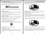
3.4 Power Connection

The four large power terminals are sized for 14 - 2 AWG (2.5 - 35
mm 2 ) wire. The terminals are rated for copper and aluminum
conductors. Use UL-listed Class B 300 Volt stranded wire only. Good
system design generally requires large conductor wires for solar module and battery
connections that limit voltage drop losses to 2% or less.

The table below provides the recommended minimum wire size allowed for the charger.
Wire types rated for 75°C and 90°C are listed.

Minimum Wire Size

Wire size

Recommended wire size:

Typical Amperage                Wire Type                      75° °C Wire                   90° °C Wire

Copper                      4 AWG (25 m

 )              6 AWG (16 m

 )

Aluminum                 2 AWG (35 m

 )               4 AWG (25 m

Copper                      4 AWG (25 m

 )              6 AWG (16 m

 )

Aluminum                 2 AWG (35 m

 )               4 AWG (25 m

Copper                      2 AWG (35 m

 )              4 AWG (25 m

Copper                       2AWG(35 m

)                 2AWG(35 m

)

45A

80A

100A

120A

60A

PV+

PV-

BATTERY-

MPPT solar charge controller

MPPT solar charge controller

Copper                      2 AWG (35 m

 )              2 AWG (35 m

Copper                      8 AWG (10 m

 )              8 AWG (10 m

 )

Aluminum                 6 AWG (16 m

 )              6 AWG (16 m

30A

Summary of Contents for MPPT

Page 1: ...USER GUIDE MPPT solar charge controller MPPT solar charge controller Make life full of hope 358 010003 04 ...

Page 2: ... 6 4 OPERATION 7 4 1 Power Up 7 4 2 Operation and Display Panel 7 4 3 LCD Display Icons 8 4 4 LCD setting 9 12 4 5 Reference Code 12 5 CHARGING LOGIC 13 5 1 3 stage Charging 13 5 2 Equalize Stage 14 5 3 Setting Parameter and Default Value 15 6 TROUBLE SHOOTING 16 7 SPECIFICATIONS 17 18 8 MPPT charger controller match to the Inverter 19 8 1 Match the inveter to the MPPT controller 19 8 2 Matching M...

Page 3: ...rt circuit batteries or other electrical parts and could cause an explosion 8 Please strictly follow installation procedure when you want to disconnect PV or battery terminals Please refer to Installation section of this manual for the details 9 GROUNDING INSTRUCTIONS This charger should be connected to a permanent grounded wiring system Be sure to comply with local requirements and regulation to ...

Page 4: ...below 3 1 Unpacking and Inspection Consider the following points before selecting where to install This solar charge controller is designed in IP31 for indoor applicationsonly Do not mount the unit on flammable construction materials Mount on a solid surface Install this charger at eye level in order to allow the LCD display to be read at all times For proper air circulation to dissipate heat allow...

Page 5: ...ct switches are both turned off before connecting power wires to the charger There are no disconnecting switches inside the charger 2 Make 4 power wires first Remove insulation sleeve 10 5mm and the conductor should be plated Tin Refer to the chart below 3 Pull all wires into the wiring box The Remote Temperature Sensor and Battery Sense wires can be inside the conduit with the power conductors It i...

Page 6: ... A battery must be connected to the controller before operating it The controller will not operate only with solar input Solar input can trigger the controller to start up when the battery is connected without pressing the button Turn on battery disconnect switch first And press operation button for a while Then it will indicate a successful start up in LCD display Turn on solar disconnect switch I...

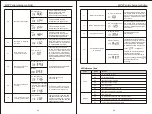
Page 7: ...arameter 05 is set as one of 12V 24V 48V If you want to set Lib first set the 05 battery rated voltage MPPT 45A 12 24V can t set theAbsorption voltage to 48v LIb mode can t set the AUO then set 02 to LIb AGM Setting Programs 0 0 Program Description Options Exit setting mode Escape Maximum charging current 0 1 45A Default Setting range is from 30A 45A 60A 80A 100Aor 120A Increment of each short pres...

Page 8: ...each short press is 0 1V The value will jump back to 12 0V after 15 5V is achieved If this program is selected to modify the changeable figure will be shown as below 1 0 The maximum current of battery equalization 15A Default The setting range is from 30A 45A 60A 80A 100Aor 120A Increment of each short press is 1A The value will jump back to 30A 45A 60A 80A 100A or 120A is achieved 0 6 Battery C V ...

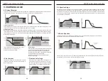
Page 9: ...arge stage charge current begins to flow typically at the maximum rate of the charge source The controller will supply solar power to charge battery as much as possible 2 Absorption stage When battery charging voltage is reached to Absorption voltage point the charging stage changes from bulk charge to Absorption Constant voltage regulation is used to maintain battery voltage at the Absorption stag...

Page 10: ...ill supply solar power to charge battery as much as possible until battery voltage raises to battery equalization voltage Then constant voltage regulation is applied to maintain battery voltage at the battery equalization voltage The battery will remain in the Equalize stage until setting battery equalized time is arrived Equalize charging time and timeout ABSORPT BULK FLOAT Equalize Voltage EQUAL...

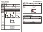
Page 11: ...ns Maximum Solar Input Voltage 12VDC 24VDC 48VDC PV Array MPPT Voltage Range Maximum Input Power 12V 625W 12V 625W 12V 825W 12V 1100W 12V 1375W 12V 1650W 24V 1250W 24V 1250W 24V 1650W 24V 2200W 24V 2750W 24V 3300W 48V 2500W 48V 3300W 48V 4400W 48V 5500W 48V 6600W MODEL Maximum Battery Current Nominal System Voltage 30Amps 45Amps 45Amps 60Amps 80Amps 100Amps 120Amps 12V 24V 48V DC Auto detection 14...

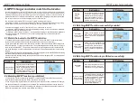
Page 12: ...nverter it needs to disable the function matching MPPT first 2 Limited the charging current of the inverter The methods are as follows a When the MPPT charging current inverter setting charging current the maximum allowable charging current of the inverter equal to 0 b When the MPPT charging current inverter setting charging current themaximum allowable charging current of the inverter equal to inv...

Reviews: