05
06
The RTS cable may be pulled through conduit along with the power wires. Tighten the connector screws
with 5 in-lb (0.56 Nm) torque.
NOTE:
The RTS is optional package. Please check local dealer for the details.
3.7 Battery Voltage Sense
CAUTION:
The controller will not activate temperature compensate charging function
if the RTS is not used.
CAUTION: Equipment Damage
Never place the temperature sensor inside a battery cell. Both the RTS and the battery will be damaged.
NOTE:
The RTS cable may be shortened if the full length is not needed.
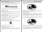
The voltage at the battery connection on the controller may differ slightly from the voltage directly at the battery
bank terminals due to connection and cable resistance. The Battery Voltage Sense connection enables the
controller to measure the battery terminal voltage precisely with small gauge wires that carry very little current,
and thus have no voltage drop. Both battery voltage sense wires are connected to the 2-pole terminal inside
of wiring box (see figure as below).
Be careful to connect the battery positive (+) terminal to the voltage sense positive (+) terminal and battery
negative (-) terminal to the voltage sense negative terminal (-). No damage will occur if the polarity is reversed,
but the controller cannot read a reversed sense voltage.
A battery voltage sense connection is not essential required to operate your controller,
but it is recommended
for best performance. The battery voltage sense will ensure
that the voltage display in LCD is very accurate.
The voltage sense wires should be cut to length as required to connect the battery to
the voltage sense terminal.
The wire size can range from 16 to 24 AWG (1.0 to 0.25mm2). A twisted pair cable is recommended but not
required. Use UL rated 300 Volt
conductors. The voltage sense wires may be pulled through conduit with the
power
conductors. Tighten the connector screws with 5 in-lb (0.56 Nm) torque.The maximum length allowed
for each battery voltage sense wire is 98 ft (30 m).
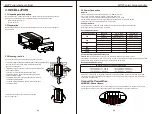
Connect terminals by following below steps (Refer to diagram above):
1. Make sure that the system input and output disconnect switches are both turned
off before connecting
power wires to the charger. There are no disconnecting switches inside the charger.
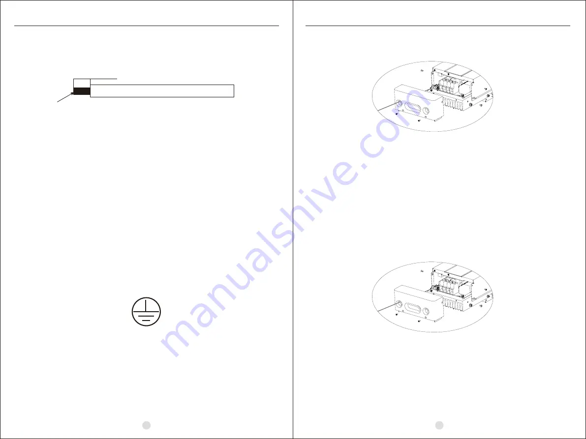
2. Make 4 power wires first. Remove insulation sleeve 10.5mm and the conductor should be plated Tin.
Refer to the chart below.
3. Pull all wires into the wiring box. The Remote Temperature Sensor and Battery Sense wires can be
inside the conduit with the power conductors. It is easier to pull RTS and Sense wires before the power
cables.
10.5mm
Tin Plating
WARNING: Risk of Damage
Be sure that the battery connection is made with correct polarity. Turn on the battery breaker/disconnect
and measure the voltage on the open battery wires BEFORE connecting to the controller. Disconnect the
battery breaker/disconnect before wiring to the controller.
4. Connect positive terminal (+) of battery to the battery positive terminal (+) on the controller.
5. Connect negative terminal (-) of battery to one of the Common Negative terminals (-) on the controller.
WARNING: Risk of Damage
Be sure that solar connection is made with correct polarity. Turn on the solar breaker/disconnect and measure
the voltage on the open wires BEFORE connecting to the controller. Disconnect solar breaker/disconnect
before wiring to the controller.
6. Connect positive wire (+) of solar module to the solar positive terminal (+) on the controller.
7. Connect negative wire (-) of solar module to one of the Common Negative terminals
(-) on the controller.
8. Screw four (4) power terminals tightly with 50 in-lbs torque. (5.65 Nm)
3.5 Grounding and Ground Fault Interruption
Use a copper wire to connect the grounding terminal in the wiring box to earth ground.The grounding terminal
is identified by the ground symbol shown below that is
stamped into the wiring box just below the terminal:
The minimum size of the copper grounding wire is 8 AWG (10 mm2).
WARNING: Risk of Fire
DO NOT bond system electrical negative to earth ground at the controller.
The included Remote Temperature Sensor (RTS) is recommended for effective temperature compensated
charging. Connect the RTS to the 2-pole terminal (see figure as below). The RTS is supplied with 33 ft (10 m)
of 22 AWG (0.34 mm2) cable. There is no polarity, so either wire (+ or -) can be connected to either
screw terminal.
3.6 Remote Temperature Sensor
MPPT solar charge controller
MPPT solar charge controller


