6
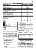
Nominal cross section of
conductor
Max. length
0.75 mm
2
1 mm
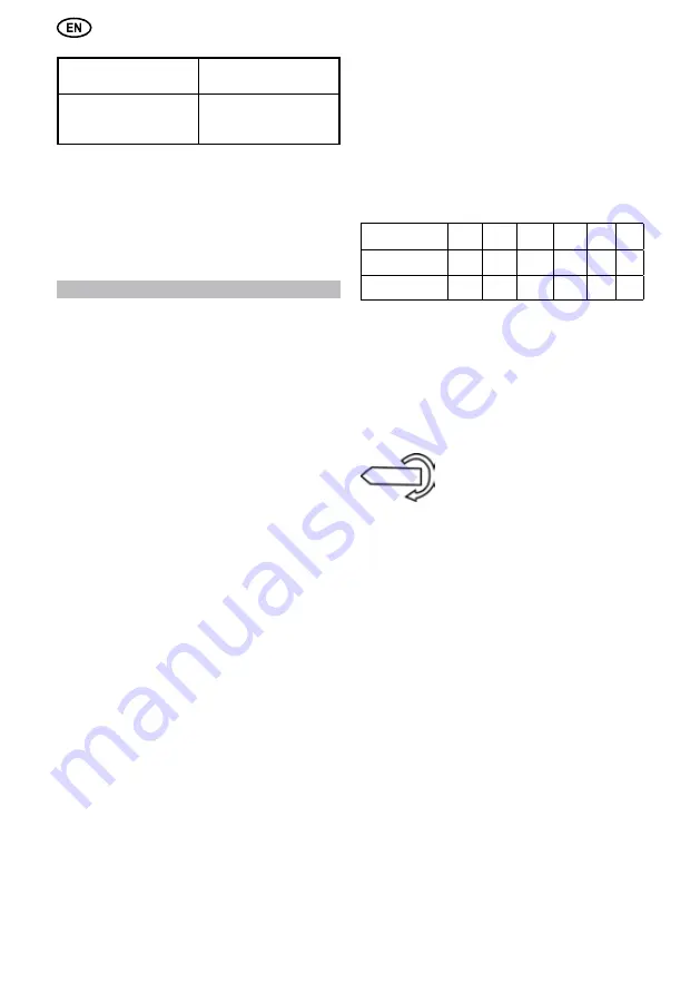
2
1.5 mm
2
30 m
40 m
60m
Maintenance and Checking of Work Area
Work area must be checked using CAUTIONs in this
manual to ensure it provides appropriate environment.
Switch Status Check
If the power plug is connected when the power switch
is in ON position, sudden rotation of the moving parts of the
Electric Rotary Hammer may cause accident.
Check if the switch lever returns to its original position
when it is pushed and pulled.
OPERATION
1. Mounting the Side handle and Stopper(Fig. 2)
For operating convenience , the side handle can be
installed in front position. Always operate the tool with the
side handle properly assembled to maximize control of the
power tool.
Mounting the side handle
1. Loosen the side handle by turning the handle
counterclockwise.
2. Slide the band over the retainer and onto the cylindrical
section at the front end
3. Mount the bolt holder and band holder, insert the hex
bolt (M8).
4. Screw the side handle to band holder.
5. Swing the side handle to the desired position.
6. Tighten the side handle by turning clockwise.
Mounting the stopper
1. Installing bit into the tool and loosen stopper holder.
2. Place drill bit onto a surface, adjust the stopper to de
-
sired depth of hole. Using the stopper will allow you to drill
a hole the depth of the distance between the bit and the
stopper.
3. Tighten the stopper holder.
2. Installing and Removing the bit CAUTION
WARNING!
Wear protective gloves when changing bit
as the bit may get hot during use.
Installig and Removing the SDS-max bit (
RH-
F40/1100VERT
,
RHF40/1100VERTM
) (Fig. 3)
1. Turn off tool and disconnect from power supply.
2. Clean the bit shank and apply grease before inserting
the bit.
3. Check that the dust cap is clean and in good condition.
Clean the dust cap if necessary or have it replaced if the
dust cap is damaged.
4. Insert the bit into the tool. Turn the bit and push it in until
engages in.
5. After installing, always make sure that the bit is securely
held in place by trying to pull it out.
6. To remove the bit, pull out the bit while pushing the re
-
tainer backward in the direction of the arrow.
3. Soft Start
The soft start feature allows you to build up speed
slowly, thus preventing the drill bit from walking off the in-
tended hole position when starting. The soft starter feature
also reduces the immediate torque reaction transmitted to
the gearing and the operator if the tool is started with the
drill bit in an existing hole.
4. Safety Clutch
The safety clutch will actuate when a certain torque
level is reached. The motor will disengaged from the output
shaft. When this happens, the bit will stop turning. This fea
-
ture prevents the gearing and motor from stalling.
CAUTION!
As soon as the safety clutch actuates,
switch off the tool immediately.
5. Speed Change (Fig. 4)
The revolutions and blows per minute can be adjusted just
by turning the controller knob. The knob is marked 1(mini
-
mum speed) to 6(maximum speed). Refer to the table be
-
low for the relationship between the number settings on the
controller knob and the R.P.M/B.P.M.
Number on
Controller knob
1
2
3
4
5
6
Revolutions per
minut
235
265
320
380
440
500
Blows per
minite
1350
1520
1840 2180
2530
2870
6. Mode Select (
RHF40/1100VERT
,
RHF40/1100VERTM
) (Fig. 5)
The
RHF40/1100VERT
,
RHF40/1100VERTM
can be
used in two operating modes. In hammer drilling mode, the
tool simultaneously rotates and impact the work. This mode
is appropriate for all concrete and masonry operations. In
the hammering-only mode, the tool only impacts the work
without rotating. This mode is appropriate for light chipping,
chiseling, and demolition applications
7. Adjusting and Fixing of Bit Angle (Fig. 6)
The bit can be adjusted to 16 different
positions (in 22.5 increments). To
change the bit angle,
set the change lever to the symbol.
Turn the selector desired angle. This ensure that plat
chisels and shapes chisels can always
be set to optimum working positions.
8. Indicator LEDS (Fig. 7)
The green power-ON indicator LED lights up when the
tool is plugged. If indicator led does not light up, the mains
cord or the controller may be detective. The red service
indicator LED lights up when the carbon Brushes are worn
out to indicate that the tool needs servicing.
After approximately 8 hours of use, the motor will
automatically be shut off.
9. Operation
Hammer drilling operation (Fig. 8)
1. Turn the change lever until it engages in the hammer
drilling position.
2. Insert the appropriate drill bit
3. Fit and adjust the side handle.
4. Position the bit at the desired location for the hole, then
pull the trigger switch.
5. Push with only enough force so that the hammer beats
smoothly.
6. Keep the tool in position and prevent it from slipping
away from the hole.
7. Do not apply more pressure. This will not make the
hammer drill faster. Lower pressure extends the life of the
bit.
8. To stop the tool, release the trigger switch. Always turn
the tool off when work is inished and before unplugging.
Chipping and Chiseling
1. Turn the change lever until it engages in the hammering
position.
2. Insert the appropriate chisel.
Summary of Contents for RHF40/1100VERT
Page 1: ...RHF40 1100VERT RHF40 1100VERTM ROTARY HAMMER MARTEAU PERFORATEUR MARTILLO PERFORADOR...
Page 2: ...2 Original Instructions...
Page 8: ...8 Traducci n de las instrucciones originales...
Page 22: ...22...
Page 23: ...23 1 b 2 b d f 3 b d f g 4 b d...
Page 24: ...24 f g h i 5...
Page 29: ...29 Y 40 80 FELISATTI FELISATTI...
Page 30: ......
Page 31: ......


