IA // ROUTING MANUAL
10
IA with Shimano Di2 Electronic Drivetrain (with Standard Junction A)
PARTS
(2) Brake hoses
(6) Shimano E-tube wires
(1) Shimano “Y” E-tube connector (Shimano part number EW-JC130)
(1) Shimano Junction B
(1) Shimano Junction A (Standard)
(1) Felt 8mm port, 2.5mm hole, conical grommet (“8mm/2.5mm conical grommet”)
(1) Felt 8mm port, 2.5mm hole, flat grommet (“8mm/2.5mm flat grommet”)
NOTE
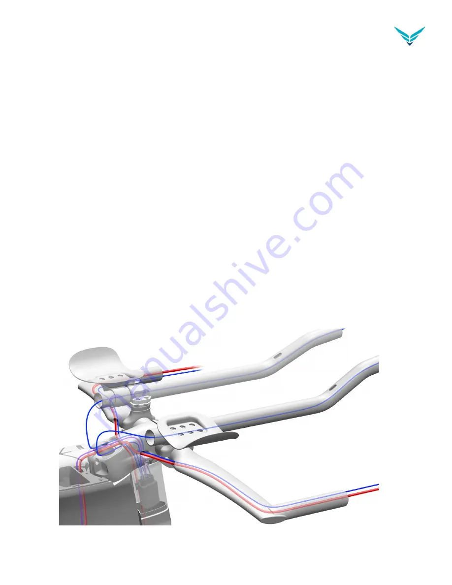
In the following diagrams, blue, purple, and green components are electronic wires; and red compo-
nents are brake hoses.
SHIFTERS
STEP 1
Start at the basebar. See Figure B1. Using a Shimano “Y” E-tube connector (Shimano part number
EW-JC130), connect its two electronic shift wires located where the brake levers will go, and connect to
the 4-port Junction A box located under the front cover. Connect an electronic wire (850mm) to each
shifter located in the aerobar extensions, and then connect them to the Junction A box located under
the front cover.
Figure B1


