FEMA ELECTRÓNICA . Series M . M40-A
8
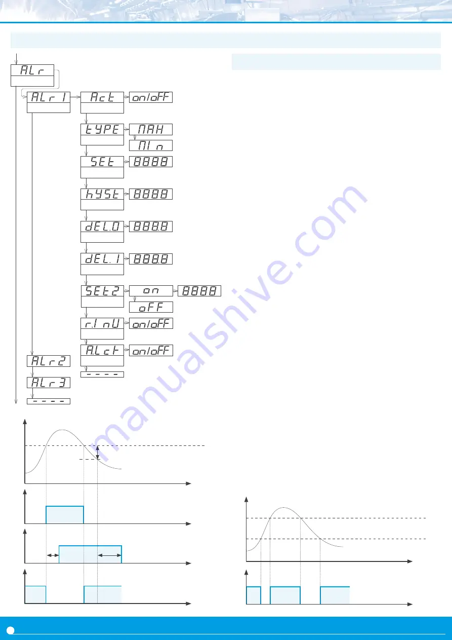
Alarm 1
Setpoint
Hysteresis
Setpoint 2
Active
Alarm type
Alarms
Activation delay
Deactivation delay
1.12 Configuration menu (cont.)
the ‘
Alarms
’ (‘
ALr
’) menu configures the independent activation of
up to 3 relay outputs, installed with the R1 optional modules
section 2.1). For outputs up to 4 and 6 relays, see special modules R2,
R4 and R6 at section 2.6. the alarm states are indicated in the front
display with leds marked as ‘1’, ‘2’ and ‘3’.
To configure an alarm, enter into the alarm menu (‘
ALr1
’, ‘
ALr2
’ or
‘
ALr3
’) and configure the following parameters :
• select ‘
Active
’ (‘
Act
’) to ‘
on
’
• at ‘
Alarm type
’ (‘
TypE
’) select the alarm acting as a maximum
type alarm (‘
MAX
’) or a minimum type alarm (‘
MIn
’). the maxi-
mum type alarm (or minimum type alarm) activates when the dis-
play value is higher (or lower) than the setpoint value.
• at ‘
Setpoint
’ (‘
SEt
’) enter the value for the alarm activation point
.
This parameter is eligible for configuration through the ‘
Fast access
’
• configure the hysteresis value at ‘
Hysteresis
’ (‘
hySt
’). The hys-
teresis applies to the deactivation process of the alarm. The alarm
deactivates when the reading has passed the setpoint value plus
the hysteresis value. Hysteresis helps to avoid repetitive switching
of the alarm relays, due to fluctuating input signals around the set-
point.
• at ‘
Activation delay
’ (‘
dEL.0
’) configure the delay to apply before
alarm activation. The activation delay starts counting when the set-
point value is passed. Value from 0.0 to 99.9 seconds.
• at ‘
Deactivation delay
’ (‘
dEL.1
’) configure the delay to apply
before alarm deactivation. The deactivation delay starts counting
when the setpoint value plus the hysteresis value, is passed. Value
from 0.0 to 99.9 seconds.
• to work with ‘windowed alarms’ (see graphical example below)
activate ‘
Setpoint
2
’ (‘
SEt2
’) to ‘
on
’ and then configure the desired
second setpoint value. Second setpoint must always be higher in
value than the first setpoint.
• the ‘
Relay inverted
’ (‘
r.Inv
’) parameter inverts the normal relay
connections. When set to ‘
on
’ the relay will be active when alarm is
inactive. For security applications where an inactive relay controls
the shutdown of the system.
• the ‘
Locked alarm
’ (‘
A.Lck
’) parameter disables the automatic
deactivation of the alarm. Alarm deactivation must be performed
manually, by pressing the ‘LE’ front button (see section 1.12.8)
1.12.3 Alarms
reading
time
setpoint
hysteresis
Alarm as maximum,
no hysteresis, no delays
on
off
time
activation
delay
on
off
deactivation
delay
time
Alarm as maximum,
with hysteresis and delays
on
off
time
Alarm as minimum,
no hysteresis, no delays
reading
time
Setpoint 2
Setpoint 1
Alarm as minimum,
with double setpoint,
no hysteresis, no delays
on
off
time
Relay inverted
Locked alarm


