FEMA ELECTRÓNICA - Page 3
User¨s Manual - Series MAG983-X
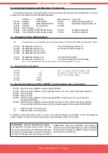
4.1 .- Trigger Levels for NPN, PNP, NAMUR signals
Jumper H,G Closed
Jumpers H,G open
Trigger Level LOW
Trigger Level HIGH
Logical «1» >3.75 Vdc
Logical «1» >7.50 Vdc
Logical «0» <1.50 Vdc
Logical «0» <5.50 Vdc
4.2 .- Antirrebound Filters .- Jumpers J,K
Closed.-
Antirrebound filters at <100 Hz
Open .-
Antirrebound filters at <10KHz
Note .- Use filter <100Hz for input type mechanical contact,
in order to filter contact rebounds
4.3. - Frontal Reset.- Jumper L
Closed .-
Enables front button for RESET
Jumper L
G
H
J
K
4.- Internal Jumpers (Trigger Levels, Antirrebound Filters, Front Reset ):___________
The «RESET» connection at the
rearside terminal is operated with a
mechanical contact connected at
terminals 7 and 3. Power is connected
at terminals 1 and 2.
6.- Power connections and Rearside Reset____________________________________
Connections for
POWER SUPPLY
Connections for
RESET
RESET
Common
The rear side of the instrument shows the terminals for
connecting signals, power of the instrument, and contact for
«RESET», and the jumpers for signal type selection
(Jumpers A,B,C,D,E,F)
5.- Rear side view________________________________________________________
Input1
Power
7 6 5 4 3 2 1
FEDCBA
Vexc
(+10Vdc)
Input2
Reset
+
-
Negative
Sign LED
48
(1,89)
96
(3,78)
2.- Mechanical Dimensions (mm / inches)___________________________________
13
(0,51)
102
(4,02)
15
(0,59)
5 max
(0,20)
123456789012345678
123456789012345678
123456789012345678
123456789012345678
123456789012345678
123456789012345678
123456789012345678
123456789012345678
123456789012345678
123456789012345678
Panel Cutout
92,5
x 44,5
(3,64 x 1.75)
~
~
+
-
7 6 5 4 3
2 1
The frontal of the MAG983 instruments shows the 6 displays
for counting value, the led for negative sign polarity indication,
and the «RESET» push button. This button can be disabled
acting on jumper L
(See section 4.3)
3.- Front View__________________________________________________________
RESET


