background image

13

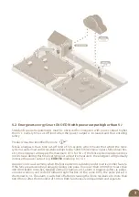
Connecting output

   Connect the 

black earthing output

 to the earthing rod using earthing cable.

      Connect the 

red output

 to the fence system using the connecting cable.

Yellow output

 is intended for connecting fence system where we always require reduced 

energy in order that animals receive weaker, approximately half strength impulse; this 

relates to fence system for younger and smaller animals (foals, calves). It is also connected 

separately to the larger fence system lower wire, where vegetation is expected to be 

dense with technical measures to prevent losses, namely voltage leakage to the ground 

as it is usual in standard connections thus the energizer power output is not reduced. The 

other wires connected to the red output are powered separately at full voltage.

Green output

 is intended for measuring the quality of earthing to find out whether the 

existing earthing is satisfactory or requires upgrading due to the location, e.g. adding 

another earthing rod, irrigate it or repair connections. It is always required to install 

measuring electrode located 10 m from the energizer earthing point. Use non-corroding 

well conducting rod at least 20 cm long for the measuring electrode. Connect high voltage 

cable to the green energizer connection.

Ground voltage shown 

on the energizer display

Status

0 to 0,20 kV 

OK

0,20 to 0,50 kV 

Check earthing; add another earthing 

rod as a precaution

> 0,5 kV 

Carry out repairs or add earthing rod

It is also important what fence system impedance the energizer measures. If the energizer 

shows impedance of 500 Ohm or lower, i.e. long or overgrown fence system then there is no 

need to install anything else and the earthing check works automatically. Check the ground 

voltage on the energizer according to the below table.

If the fence system impedance is higher than 500 Ohm, i.e. quality fence not subjected to 

load, then it is required to short-circuit the fence system to enable the measurement and thus 

determine the quality of earthing. To carry out short-circuiting, the overhead fence system 

wire is earthed at a location of at least 50 m from the energizer. Use good quality earthing rod, 

hammer it into the ground and connect it to the wire, subsequently check the ground voltage 

on the energizer according to the following table.

Summary of Contents for energy Smart DUO EDW100

Page 1: ...E OUTPUT VOLTAGE500 SWITCHING ON OFF energySmartDUOEDW100 13 J 10 J 10 500V 7 500 V energySmartDUOEDW150 20 J 15 J 10 500V 7 500 V 300 km 90 km 22 km 10 km 350 km 120 km 28 km 16 km Electric fencing S...

Page 2: ...ing the device carefully and to keep it for possible application in the future Electric fence must be constructed so that persons are protected against unintentional contact with pulses conductors und...

Page 3: ...han 5 J 7 5 3 List of main advantages 8 6 Product description 9 7 Ready to use 10 8 Control 14 9 Explanation of LED indicating lights and bargraph indicator 15 10 Display 16 10 1 Main screen 17 10 2 I...

Page 4: ...connected directly to the panel Switch off the energizer before carrying out any work on the electric enclosure fence Read thoroughly the Safety Guidelines paragraph Strictly observe all safety guide...

Page 5: ...in the desired deterrent effect The impulse lasts for a matter of milliseconds These fences serve not only to enclose an area but also act as a deterrent e g to protect against wild boars Benefits of...

Page 6: ...using quality fence system with a low load It also optimises energy consumption to maintain adequately high fence system voltage which is for example overgrown with grass high load LED indicator ligh...

Page 7: ...the fence system resistance does not increase during this time carrying out corrective measures the energizer will gradually increase the power output e g EDW150 model up to 15 J Acoustic and visual...

Page 8: ...of earthing Cloud connection Direct connection via Wi Fi router Power switching Manual switching between the high and low power output option for reducing demand on the battery Up to date information...

Page 9: ...nce system voltage 6 Push button for selecting particular display 7 Push button used for confirming Changing values 8 ON OFF button 9 Earthing black 10 Connection for measuring the quality of earthing...

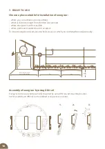
Page 10: ...t water stream is avoided To mount energizer on wall use attached screws on which you can hang the energizer easily Assembly of energizer by using DIN rail Energizer can be easily and practically moun...

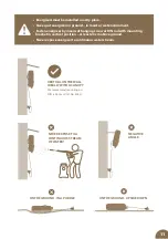
Page 11: ...WITH A CANOPY We recommend mounting on DIN rail 80 mm Art No 8043 Energizers must be installed in a dry place Never put energizer on ground in moist or wet environment Fasten energizer by means of han...

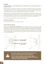
Page 12: ...lace with maximum and permanent humidity On dry pieces of land or in case of soils with lower electric conductivity use one or several supplementary earthing rods with length of minimum of 1 m and pla...

Page 13: ...easuring electrode located 10 m from the energizer earthing point Use non corroding well conducting rod at least 20 cm long for the measuring electrode Connect high voltage cable to the green energize...

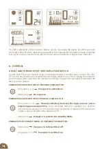
Page 14: ...2 s Manual switching between the high and low power output approximately 50 User selectable when for example it is used for more sensitive animals or to reduce demand on battery if required The low po...

Page 15: ...ICATOR To indicate input voltage at fence system energy Smart DUO EDW models are equipped with BARGRAPH indicator It consists of six LEDs 2x RED I 2x YELLOW I 2x GREEN ordered from left to right BARGR...

Page 16: ...cally resistance of the fence but also graphically with an icon of overgrown grass Setting screen On the first and second screens you can select between the displayed parameters using the Confirmation...

Page 17: ...ation about the status of the connection to the server The indication has two states A triangle may appear instead of the connection symbol in the event of an alarm Or the E1 E2 error symbol if it occ...

Page 18: ...ing the 50 100 mode Indicating the displayed parameter Triangle indicating a warning Hourglass indicates a time delay before ramping up the performance Icons on the display Error message see point 12...

Page 19: ...hm medium pen with mild growth of vegetation 500 ohm longer pen mild growth of greenery 300 ohm longer pen medium growth of greenery or mild growth after rain 300 ohm a pen with a dense growth of vege...

Page 20: ...0 kV the voltage alarm is off Light Setting the backlight time Here you can set the values of 1 minute 5 minutes and continuous light ON Contrast Setting the display contrast in the range 90 150 The f...

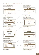
Page 21: ...ngs button to enter the settings screen Settings screen Use the enter button to enter the settings Entering the settings menu Use the settings button to select an item Selection of a required item Use...

Page 22: ...ing configuration can be changed at any time by starting a new configuration If the item is marked it means that no Wi Fi configuration is stored in the energizer Connected Indicates a successful conn...

Page 23: ...select the energizer you want to configure The name of the energizer is listed on the label in the box along with the MAC address and PIN 5 Select your Wi Fi and enter the correct password a pairing...

Page 24: ...alled along the public roads must be marked with warning signs attached to poles or fences at regular intervals and visible from the road Warning sign It is of yellow colour with minimum dimensions of...

Page 25: ...rts If one wire is connected with a metal part ie a gutter or a metal structure of the building these metal parts must be grounded A warning sign shall be fitted to every point where persons may gain...

Page 26: ...on again For this purpose connection to network with earth leakage circuit breaker must be available For purposes of testing connect earthing output of energizer to protective conductor of the supplyn...

Page 27: ...is provided with guarantee period of 3 years according to our conditions for guarantee Safety instructions earthing putting into operation care of batteries and accumulator conditions for guarantee an...

Page 28: ...ry from its deep discharge and battery destruction Replace the battery with a sufficiently charged one or connect adapter until battery voltage reaches at least 12 V red LED will be burning Lead in or...

Page 29: ...vice Department for a specialist inspection and repair Displayed error message E2 Processor communication error Energizer works but cannot be controlled remotely It is necessary to send the energizer...

Page 30: ...D DISPLAY ON OFF LED ON OFF LED IMPULS LED LOW BATTERY VOLTAGE LED POWER LOWER 50 LED ERROR CHECK LED IMPULS BARGRAF REDUCED POWER OUTPUT MEASURING OF EARTHING TIME DELAY TEOR MAX CEE 300 km 350 km LO...

Page 31: ...free for download You can turn the device on and off remotely change the power Possibility to set the voltage drop values when the alarm is triggered Alarm record for each device Graphical display of...

Page 32: ...an kroun Czech Republic info fencee eu 420 730 893 828 Customer service 420 730 893 827 19042023 Print fencee cz fenceeczech Electric fencing www fencee eu www fenceefarm com www fenceecloud com Smart...

Reviews: