background image

2

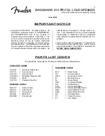
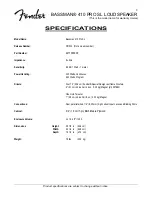
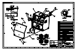
BASSMAN® 410 PRO SL LOUDSPEAKER

(This is the model name for warranty claims)

June, 2002

IMPORTANT NOTICE

 Copyright © 2002 FMIC.  All rights reserved.  All

information contained herein is CONFIDENTIAL
and PROPRIETARY and is the property of
Fender® Musical Instruments Corporation.  It is
not to be sold or assigned to another party and is
disclosed solely for use by Fender Authorized
Service Centers for purposes of product service
and maintenance.  All information is not to be dis-
closed to others without the expressed permission
of Fender® Musical Instruments Corporation.  All

specifications are subject to change without no-
tice.  This information and any copies produced
electronically or otherwise must be surrendered
upon demand of Fender Musical Instruments Cor-
poration.

 Parts marked with two asterisks (

**

) indicate the

required use of that specific part.  This is neces-
sary for RELIABILITY and SAFETY requirements.

DO NOT USE A SUBSTITUTE! 

PARTS LIST CODES

The description codes used in the itemized Parts Lists are defined below:

CAPACITOR  CODES

CAP AE

=

Aluminum Electrolytic

CAP CA

=

Ceramic Axial

CAP CD

=

Ceramic Disk

CAP MPF =

Metalized Polyester Film

CAP MY

=

Mylar

CAP PFF

=

Polyester Film/Foil

RESISTOR  CODES

RES CC

=

Carbon Comp

RES CF

=

Carbon Film

RES FP

=

Flame Proof

RES MF

=

Metal Film

RES WW

=

Wire Wound

HARDWARE  CODES

BLX

=

Black Oxide

CR

=

Chrome Plated

HWH

=

Hex Washer Head

M

=

Machine Screw

NI

=

Nickel Plated

OHP

=

Oval Head Phillips

PB

=

Particle Board

PHP

=

Pan Head Phillips

PHPS

=

Pan Head Phillips Sems

SMA

=

Sheet Metal "A" Point

SMB

=

Sheet Metal "B" Point

SS

=

Stainless Steel

TF

=

Thread Forming

ZI

=

Zinc Plated

Summary of Contents for 410 PRO

Page 1: ... Fender Musical Instruments Corp 8860 East Chaparral Road Suite 100 Scottsdale AZ 85250 p n 2217000000 120V SERVICE MANUAL CONTENTS Notices 2 Specifications 3 Service Notes 4 Parts Lists PCB Assembly 5 Input Assembly 5 Cabinet Assembly 5 End Item Assembly 5 Service Diagrams 6 ...

Page 2: ... must be surrendered upon demand of Fender Musical Instruments Cor poration Parts marked with two asterisks indicate the required use of that specific part This is neces sary for RELIABILITY and SAFETY requirements DO NOT USE A SUBSTITUTE PARTS LIST CODES The description codes used in the itemized Parts Lists are defined below CAPACITOR CODES CAP AE Aluminum Electrolytic CAP CA Ceramic Axial CAP C...

Page 3: ...ower Handling 300 Watts Continuous 600 Watts Program Drivers Four 10 25 4 cm Fender Special Design cast frame Woofers 2 5 1 cm Voice Coil 44 oz 1 25 kg Magnet p n 057982 One Horn Tweeter 1 2 5 cm Voice Coil 8 oz 0 23 kg Magnet Connections Dual parallel wired 1 4 6 35 mm high current Input Jacks and Binding Posts Cabinet 3 4 1 9 cm 7 ply Birch Maple Plywood Enclosure Volume VB 4 4 ft3 125 l Dimensi...

Page 4: ...r to remove the blown lamp which is visible through a cutout in the circuit board 4 Remove the spare lamp stowed on the side of the circuit board and install it where the blown lamp was removed 5 Install the input jack plate in the reverse of re moval PCB EXCHANGE POLICY Parts marked with a single asterisk in the Part Lists are not field replaceable If a failure due to one of these components is d...

Page 5: ...16352000 NUT HEX 3 8 32 X 3 32 TK NI 1 0057976000 PLATE INPUT BASSMAN 410 PRO 2 0031153000 WSHR FLAT 3 8 X 614 NI 2 0016436000 WSHR LCK INTL 3 8 X 687 X 035 NI PARTS LIST CABINET ASSEMBLY QTY PART DESCRIPTION REFERENCE DESIGNATION 8 0057945000 CABINET CORNER PLASTIC 2 745 0040046000 CARPET BLACK SY 2 0057946000 HANDLE SPRING LOADED 4 0056482000 MOUNTING PLATE EL COM 32 0021972000 NUT T 10 32 X STR...

Page 6: ...part Replacement must match Safety Agency Value if specified Type if specified Approval Mark s if on part Both a unique Fender part and a Safety Requirement part as defined above PARTS LIST END ITEM ASSEMBLY QTY PART DESCRIPTION REFERENCE DESIGNATION 3 0057971000 SPEAKER PORT 3 00 DIA 8 0050317000 STANDOFF RUBBER 75 DIA X 77 1 0053489000 WIRE SET FINAL SUNN 410H Schematics and Drawings Service Dia...

Page 7: ......

Page 8: ...D ...

Reviews: