5
Installation instructions
Installation, electrical connection and the first commissioning is permitted to
be performed by a worker with relevant qualifications. The panels are intended
for mounting on a wall or ceiling. The producer must be consulted before any
other form of installation is attempted.
Installation on the ceiling
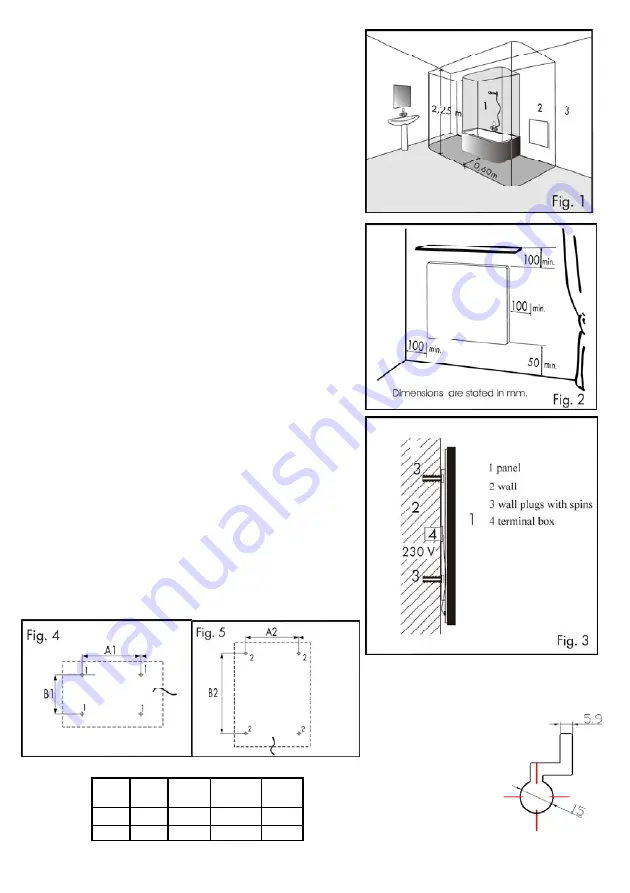
Drill the openings for mounting according to Fig. 4 or Fig. 5. The package
contains four 6 x 70mm screws for attachment. Always hang the panel by all
four mounting slots. Recommended type of wall anchors – Fischer Ux 10 (not
included in the package).
Dimensions A and B are the spacing between the drilled openings.
Installation on the wall
The panel can be installed horizontally or vertically. Drill the openings for
mounting according to Fig. 4 (horizontal installation) or Fig. 5 (vertical installa-
tion). The package contains four 6 x 70mm screws for attachment. Always
hang the panel by all four mounting slots. Recommended type of wall anchors
– Fischer Ux 10 (not included in the package).
Dimensions A and B are the spacing between the drilled openings.
Clearance distances
The distance between the bottom edge of the appliance and the floor mustn’t
be less than 50 mm; 150 mm is recommended. The clearance distance on the
side (e.g. from furniture) must be at least 100 mm, and 100 mm is the mini-
mum in the upward direction (see Fig. 2).
In bathrooms, the panel must be installed in accordance with the HD 60364-7-
701:2007 standard and is permitted to be located in accordance with Fig. 1.
The panel is a class II appliance, with IP 44 coverage. The panel must not be
placed directly under an electric socket.
W A1
(mm)
B1
(mm)
A2
(mm)
B2
(mm)
300 390 303 308 296
600 390 303 308 296
Detail of a panel
mounting slot
Summary of Contents for Ecosun G 300
Page 11: ...11...


