
2
1. Description and cennection
•
The heating cables should be connected to a 230V/400V,
50Hz electricity network. Degree of protection: IP67.
•
The cable jacket is resistant to UV radiation, jacket tem-
perature resistance is 90°C, and it is self- extinguishing.
•
The protective braiding is to be connected to the PE
protective conductor.
Construction:
•
Core: double cord stranded resistance wire
•
1
st
insulation: fluoropolymer (FEP) – thickness 0.3mm
•
2
nd
insulation: cross- linked polyethylene (XLPE) – thickness 0,8mm
•
Protective braiding: 14 tinned copper wires
∅
0.3mm +
AlPET foil
•
Jacket: cross- linked polyethylene (XLPE) – thickness 0,8mm
1. Popis a zapojení
•
Topné kabely se připojují na soustavu 230V nebo 400V,
50Hz, dle hodnoty uvedené na štítku kabelu. Krytí IP67.
•
Plášť kabelu je odolný proti UV záření, teplotní odolnost
pláště 90°C, samozhašivý.
•
Ochranné opletení se připojuje na PE vodič.
Konstrukce:
•
Jádro: 2x slaněný odporový drát
•
1. Izolace: FEP – tloušťka 0,3mm
•
Meziplášť: síťovaný polyetylen (XLPE) – tloušťka 0,8mm
•
Ochranné opletení: 14 Cu drátků Ř 0,3mm pocínovaných +
AlPET folie
•
Plášť: síťovaný polyetylen (XLPE) – tloušťka 0,8mm
2. Vyhřívání venkovních ploch (protinámrazová ochrana)
a) Dimenzování
Plošný příkon dimenzujte na volných prostranstvích jejichž
podkladní plocha je zemina a na tepelně izolovaných plochách
ve výkonu 200 až 300W/m
2
a u instalací na tepelně neizolo-
vaných plochách ve výkonu 250 až 350W/m
2
. Velikost výko-
nu mj. závisí na hloubce uložení, čím blíže povrchu, tím menší
výkon z doporučeného intervalu. V případě montáže do jemné-
ho plaveného písku nesmí instalovaný plošný výkon přesáh-
nout 300W/m
2
.
b) Montáž do betonu
Postup
•
Vytvořte zhutněnou podkladovou vrstvu štěrku 150 -
300mm, vrstvu štěrku můžete považovat za tepelnou izolaci.
•
Na armovací sít rozviňte topný kabel ve tvaru meandrů a
fixujte stahovací páskou. Topný kabel nesmí být přiliž
utažen, aby nedošlo vlivem teplotní roztažnosti betonu
k poškození kabelu.
•
Armovací síť umístěte do středu, maximálně však do 2/3
betonové vrstvy.
•
Proveďte proměření odporu topného okruhu a izolačního
odporu, hodnotu zapište do Záručního listu.
•
Zakreslete do záručního listu rozložení kabelu.
•
Kabel zalijte vrstvou betonu. Betonová vrstva musí byt
monolitická aby vlivem teplotního namáhaní nedošlo
k odtržení jednotlivých vrstev.
•
Opětovně proveďte proměření odporu topného okruhu a
izolačního odporu, hodnotu zapište do Záručního listu.
•
Betonové směsi musí osahovat příměsi chránící směs před
vnějšími vlivy.
2. Heating outside areas (anti- freezing protection)
a) Dimensioning
If the heating is intended to be used on open areas with soil as a base
and on thermally insulated surfaces, set the flat output to 200–300 W/
m
2
. If the heating is intended to be used on surfaces that are not
thermally insulated, set the output to 250–350 W/m
2
. The value of the
output depends, among other things, on the depth to which the heating
system is installed. That means that the closer the installation is to the
surface, the lower the output needs to be within the recommended
range. If installed into fine washed sand, the installed flat output must
not exceed 300 W/m
2
.
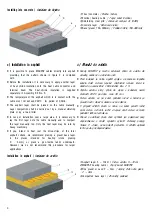
b) Installing into concrete
Procedure
•
Create a compact underlying layer of gravel 150–300 mm thick. This can
be regarded as the thermal insulation.
•
Place the heating cable in an open- looping pattern on the reinforcing grid
and fix it with fastening strips. The heating cable must not be too tightly
affixed or it could be damaged due to the thermal expansion of the
concrete.
•
Place the reinforcing grid in the middle, and at maximum 2/3 down into
the concrete layer.
•
Measure the resistance of the heating circuit and the insulation resistance
and record the measured values in the certificate of warranty.
•
Draw the scheme of the heating cable layout in the certificate of war-
ranty.
•
Cover the cable with a concrete layer. The concrete layer must be
monolithic so that individual layers do not separate due to thermal stress.
•
Measure the resistance of the heating circuit and the insulation resistance
again and record the measured values in the certificate of warranty.
•
The concrete mixtures must contain ingredients protecting it against external
effects.