www.fennerdrives.com
For technical assistance,
please call +1-717-665-2421
B-LOC
® Keyless Bushings provide a high capacity, zero-backlash
shaft/hub or coupling connection by means of a mechanical interference
fit. Please follow these INSTALLATION AND REMOVAL INSTRUCTIONS
carefully to ensure proper performance of this
B-LOC
® unit.
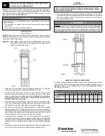
INSTALLATION
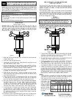
(Refer to Figure 1)
B-LOC
® Keyless Bushings are supplied lightly oiled and ready for installation.
The frictional torque capacity of these devices is based on a coefficient of friction
of 0.12 for lightly oiled screw, taper, shaft and bore contact areas.
Therefore, it is important not to use Molybdenum Disulfide (e.g., Molykote,
Never-Seeze or similar lubricants) in any Keyless Bushing installation.
1. Make sure that locking screw, taper, shaft and bore contact areas are clean
and lightly oiled with a light machine oil.
2. Insert Keyless Bushing into hub counterbore prior to shaft installation.
3. After confirming correct hub position, hand-tighten three (3) or four (4)
equally spaced locking screws until initial contact with shaft and hub bore is
established.
4. Use torque wrench and set it approximately 5% higher than specified
tightening torque (Ma). Tighten locking screws in either a clockwise or
counterclockwise sequence (it is not necessary to tighten in a diametrically
opposite pattern), using only 1/4 (i.e., 90°) turns for several passes until 1/4
turns can no longer be achieved.
5. Continue to apply overtorque for 1 to 2 more passes. This is required to
compensate for a system-related relaxation of locking screws since tightening
of a given screw will always relax adjacent screws. Without overtorquing,
an infinite number of passes would be needed to reach specified tightening
torque.
6. Reset torque wrench to specified torque (Ma) and check all locking screws.
No screw should turn at this point, otherwise repeat Steps 5 and 6.
NOTE
: 1. It is not necessary to re-check tightening torque after equipment
has been in operation.
2. In applications subject to extreme corrosion, the slits in all collars
can be sealed with a suitable caulking compound or equivalent.
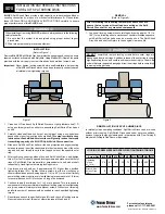
INSTALLATION OF B-LOC® KEYLESS BUSHING
OVER SHAFT KEYWAYS
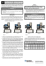
The Keyless Bushing should be positioned so that slits in Keyless Bushing
collars that contact the shaft are located approximately opposite the
keyway. In addition, a locking screw should be centered directly over the
keyway.
When tightening locking screws, it is important to follow the installation
procedure outlined above, which specifies equal 1/4 turns of each locking
screw. Failure to follow these instructions could result in excessive
tightening of the screw over the keyway, possibly causing permanent
deformation of the Keyless Bushing collars.
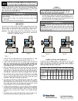
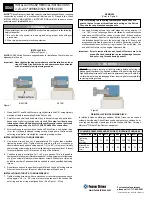
REMOVAL
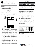
(Refer to Figure 2)
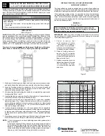
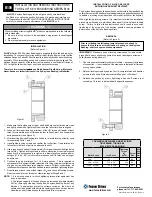
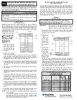
Figure 1
dB = pull-off thread, located only under cadmium plated screws of front thrust collar
Cadmium plated screws
Prior to initiating the following removal procedure, check to
ensure that no torque or thrust loads are acting on the Keyless
Bushing, shaft or any mounted components.
1. Loosen locking screws in several stages by
using approx. 1/4 turns,
following either a clockwise or counterclockwise sequence.
NOTE:
B-LOC®
Series B400 Keyless Bushings feature self-releasing
tapers, meaning collars should release during Step 1. However,
if for some reason the thrust collars jam, a light tap on three (3)
equally spaced heads of loosened locking screws will positively
release the connection.
2. Hub and Keyless Bushing are normally removed together. Removal
of Keyless Bushing only from deep counterbores is accomplished by
inserting pull-off screws (not provided) into threads located under plated
locking screws. These threads are NOT to be used for high pulling
forces, as thrust collar is only partially threaded.
©2012 Fenner Drives B-PR-016 9/17/2012
INSTALLATION AND REMOVAL INSTRUCTIONS
FOR B-LOC
®
KEYLESS BUSHING SERIES B400
B400
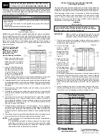
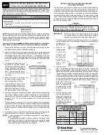
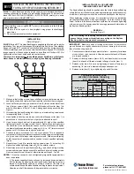
Figure 2
LOCKING SCREW SIZES AND
SPECIFIED TIGHTENING TORQUE M
a
B400 KEYLESS BUSHINGS
Metric Series
Inch Series
Tightening
Torque
Ma
(ft lb)
Screw
Size
Hex
Key
Size
(mm)
Pull-off
Thread
dB
20 x 47
to 40 x 65
3/4
to 1-1/2
11
M6
5
M8
42 x 75
to 65 x 95
1-5/8
to 2-9/16
26
M8
6
M10
70 x 110 to 95 x 135
2-5/8
to 3-3/4
51
M10
8
M12
100 x 145 to 160 x 210
3-7/8
to 6
91
M12
10
M14
170 x 225 to 200 x 260
6-7/16 to 8
138
M14
12
M16
220 x 285 to 260 x 325
214
M16
14
M20
280 x 355 to 300 x 375
293
M18
14
M22
320 x 405 to 340 x 425
420
M20
17
M24
360 x 455 to 420 x 515
565
M22
17
M27
440 x 545 to 1000 x 1110
725
M24
19
M30
WARNING
When installing or removing
B-LOC
®
products, always adhere to the following
safety standards:
1. Be sure that the system is de-energized using proper lockout/tagout
procedures.
2. Wear proper personal protective equipment.


