www.fennerdrives.com
For technical assistance,
please call +1-717-665-2421
B-LOC
® Keyless Locking Devices provide a high capacity, zero-backlash shaft/
hub or coupling connection by means of a mechanical interference fit. Please
follow these INSTALLATION AND REMOVAL INSTRUCTIONS carefully to ensure
proper performance of this
B-LOC
® unit.
WARNING
When installing or removing
B-LOC
® products, always adhere to the following
safety standards:
1. Be sure that the system is de-energized using proper lockout tagout
procedures.
2. Wear proper personal protective equipment.
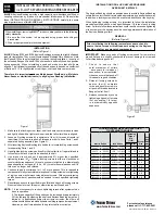
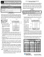
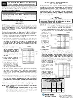
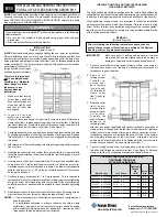
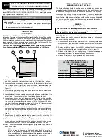
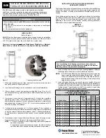
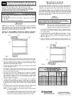
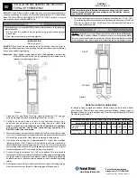
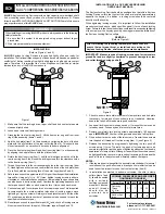
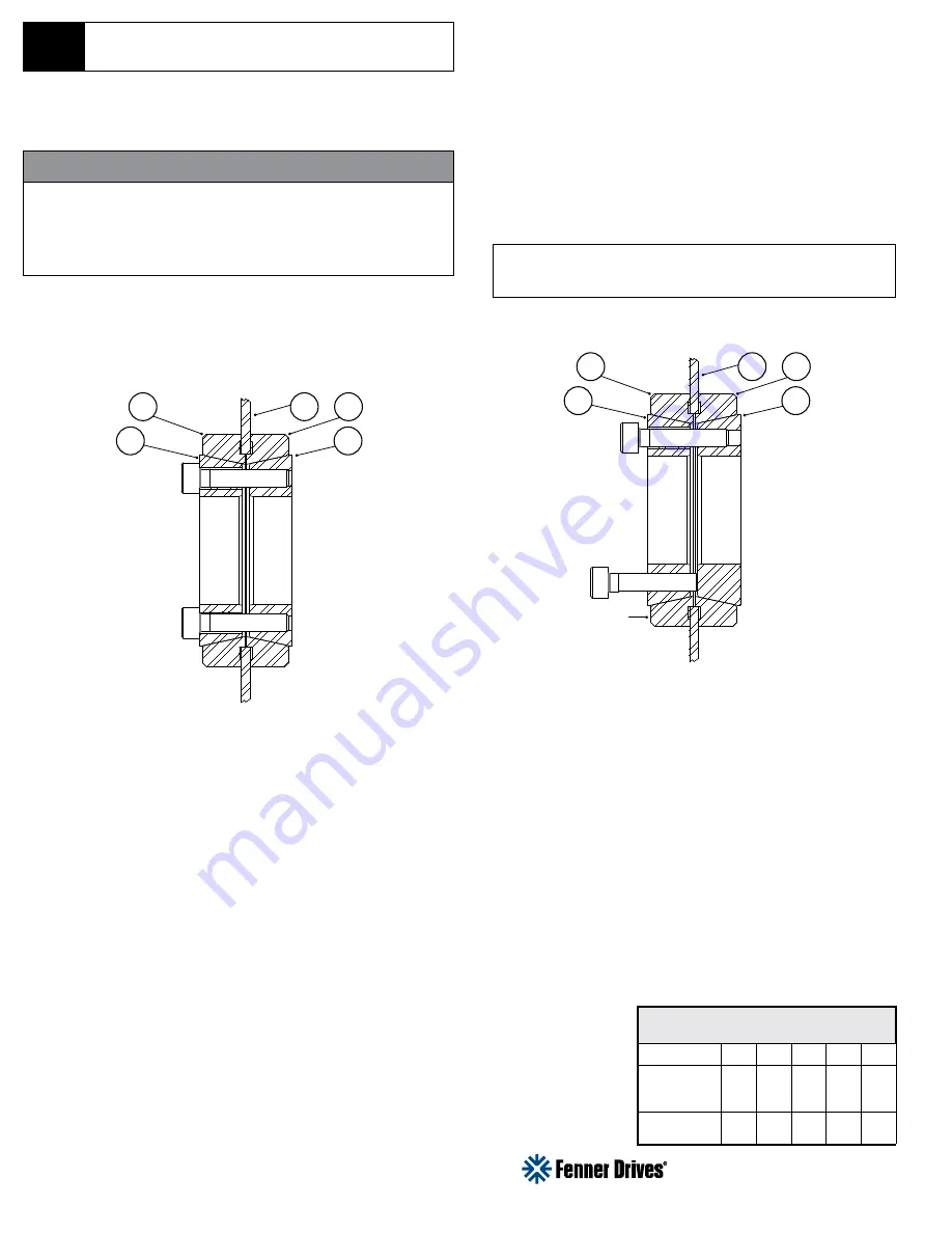
Figure 1
INSTALLATION
(Refer to Figures 1 and 2)
B-LOC®
Keyless Locking Devices are supplied lightly oiled and ready for
installation. The frictional torque capacity of these devices is based on a particular
coefficient of friction resulting from lightly oiled tapers, shaft and bore contact
areas. Therefore, it is important to not use Molybdenum Disulfide (or similar
lubricants) on any of the BLOC components.
1. Make sure that the locking device, taper, shaft and hub contact areas are
clean and lightly oiled.
2. Loosen and remove all locking screws
3. Grasping the front outer ring item 2, lift the front outer ring and front inner
ring off the assembly (items 1 and 2).
4. Add the hub plate (item 3) to the assembly by aligning the bore of the hub
plate with the pilot surface of the rear outer ring (item 4). This should be a
close clearance fit, so care should be taken to ensure alignment.
5. Place the front outer ring (item 2) and front inner ring (item 1) on the assembly
by aligning the hub plate bore with the pilot surface.
6. Rotate the front inner ring (item 1) until the slit is aligned with the slit in the
rear inner ring item 5, then insert the locking screws thru the clearance holes
in the front inner ring (item 1).
7. Thread the screws into the corresponding holes in the rear inner ring (item
5). Hand-tighten each screw, and confirm that the faces of the hub plate (item
3) are flush with the contacting face of the outer rings (items 2 and 4).
8. Set a torque wrench to approximately 5% higher than the specified installation
torque Ma. Using only ¼ (i.e., 90°) turns, tighten locking screws in either a
clockwise or counterclockwise sequence (a diametrically opposite pattern
can also be used, but is not required). Continue the tightening sequence until
the torque wrench clicks on each screw before ¼ turns can be achieved.
9. Continue to apply 5%-overtorque for one to two more passes. This is required
to compensate for a system-related relaxation of locking screws since
tightening of a given screw will always relax adjacent screws. (Without the
5% overtorque, an infinite number of passes would be needed to reach the
specified installation torque.)
10. Reset torque wrench to specified torque (Ma) and check all locking screws.
No screw should turn at this point. Otherwise, repeat Steps 9 and 10.
REMOVAL
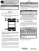
(Refer to Figure 2)
Prior to initiating the following removal procedure, check to
ensure that no torque, thrust, or radial loads are acting on the
Keyless Locking Device, shaft or any mounted components.
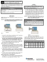
IMPORTANT! Make sure ends of locking screws used for removal are
ground flat and are slightly chamfered to prevent damage to screw
and collar threads during push-off.
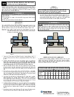
INSTALLATION OF B-LOC® KEYLESS BUSHING
OVER SHAFT KEYWAYS
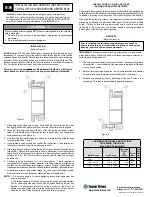
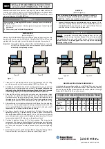
The Keyless Locking Device should be positioned so that slits in Keyless
Locking Device collars that contact the shaft are located approximately
opposite the keyway. In addition, a locking screw should be centered
directly over the keyway.
When tightening locking screws, it is important to follow the installation
procedure outlined above, which specifies equal ¼ turns of each locking
screw. Failure to follow these instructions could result in excessive tightening
of the screw over the keyway, possibly causing permanent deformation of
the Keyless Locking Device collars.
1. Check to ensure that axial movement of clamp collars and hub plate
(necessary for release of connection) are not restricted. Likewise,
ensure that push-off threads are in good condition.
2. Loosen all locking screws in sequence by ¼ turns until screws can be
turned by hand. Loosen by hand for several more turns.
3. Remove completely two locking screws approximately 180 degrees
apart.
IMPORTANT!
All other locking screws should be left in place.
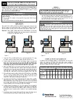
4. Grind a chamfer on the ends of the two screws. Transfer these screws
into the push-off threads of front inner ring (item 1) (see Figure 2).
5. Release the assembly by progressively tightening the two push-off
screws using ¼ turns. Typically, the push-off screws appear to be
completely tight after just one pass of tightening without any noticeable
separation of clamp collars. Although it seems that the screws cannot
be tightened further, several more rounds of torqueing will increase the
push-off force in the system and ultimately release the tapers.
NOTES:
1: If the tapers do not release after the assembly is jacked apart for several
revolutions of the push-off screws, a brass punch or similar tool can be
used to exert an impact force on the front outer ring (item 2).
2: In installations subjected to extreme corrosion, the slits in clamp
collars (items 1 and
5) should be sealed
with a suitable
caulking compound
or sealant. Likewise,
push-off threads
should also be
p r o t e c t e d f r o m
corrosion.
©2013 Fenner Drives B-PR-027 10/03/2013
INSTALLATION AND REMOVAL INSTRUCTIONS FOR
B-LOC
®
COMPRESSION HUB SERIES BCH20 & BCH50
BCH
LOCKING SCREW SIZES AND SPECIFIED
TIGHTENING TORQUE M
a
Screw Size M4
M5
M6
M8 M10
Tightening
Torque
Ma (ft lb)
3.7
7
12
30
60
Hex Key Size
(mm)
3
4
5
6
8
NOTE 1
3
1
5
2
4
3
1
5
2
4
Figure 2


