www.fennerdrives.com
For technical assistance,
please call +1-717-665-2421
B-LOC
® Split Shrink Discs provide a high capacity, zero-backlash shaft/hub or
coupling connection by means of a mechanical interference fit. Please follow
these INSTALLATION AND REMOVAL INSTRUCTIONS carefully to ensure
proper performance of this
B-LOC
® unit.
WARNING
When installing or removing
B-LOC
® products, always adhere to the following
safety standards:
1. Be sure that the system is de-energized using proper lockout tagout
procedures.
2. Wear proper personal protective equipment.
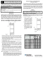
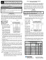
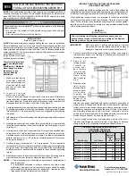
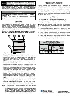
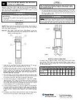
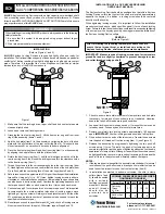
Figure 1
INSTALLATION
(Refer to Figure 1)
Remove
B-LOC®
Split Shrink Disc from protective wrapping and check to ensure
tapered surfaces are coated with Molykote. Using Molykote G-Rapid Plus paste
provided with the unit apply to screw threads and underside of screw head.
Important:
Never tighten locking screws before shaft installation, as inner ring
of Split Shrink Disc and/or hub can be permanently contracted even
at relatively low tightening torques.
1. Clean hub O.D. and each Split Shrink Disc bore. Lightly lubricate hub O.D.
using an ordinary machine oil before assembling Split Shrink Disc halves
on hub.
2. Carefully clean shaft and hub bore of any lubricant using a non-petroleum
based solvent prior to mounting hub onto shaft.
This step is critical, as any
lubricant on the shaft/hub bore interface will greatly reduce the torque
transmitting capacity of a B-LOC® Split Shrink Disc connection.
3. Slide each Split Shrink Disc half over the hub projection and align mounting
holes as required. Insert the capscrews into the clearance holes of the outer
ring and hub web; thread them into the tapped holes of the opposite outer
ring.
4. After confirming correct position of hub and Split Shrink Disc, hand-tighten
three (3) or four (4) equally spaced locking screws and make sure that outer
rings of Split Shrink Disc are parallel or perpendicular to hub web or shaft
respectively. Hand-tighten remaining locking screws.
5. Use torque wrench and set it approximately 5% higher than specified
tightening torque (M
a
). Tighten locking screws in either a clockwise or
counterclockwise sequence, using approx. 1/4 (i.e., 90°) turns (even if initially
some locking screws require a very low tightening torque to achieve 1/4 turns)
for several passes until 1/4 turns can no longer be achieved.
6. Continue to apply overtorque for 1 to 2 more passes. This is required to
compensate for a system-related relaxation of locking screws since tightening
of a given screw will always relax adjacent screws. Without over torquing,
an infinite number of passes would be needed to reach specified tightening
torque.
7. Reset torque wrench to specified torque (M
a
) and check all locking screws.
No screw should turn at this point, otherwise repeat Step 5 and 6.
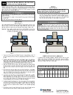
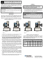
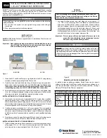
REMOVAL
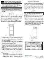
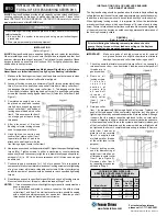
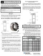
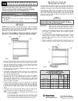
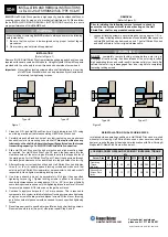
(Refer to Figure 2)
Prior to initiating the following removal procedure, check to
ensure that no torque or thrust loads are acting on the Split
Shrink Disc, shaft or any mounted components.
1. Loosen all locking screws in several stages by using approx. 1/2 (i.e.,
180°) turns, following either a clockwise or counterclockwise sequence,
until Split Shrink Disc halves can be moved on hub. The Split Shrink
Disc, hub and shaft will return to their original clearance fits.
WARNING
DO NOT
completely remove locking screws before outer rings are
disengaged from inner rings. A sudden release of the outer ring involves
high separating forces and could result in permanent injury or death. Be
certain that outer rings are disengaged from inner rings before completely
removing locking screws.
REINSTALLATION OF SPLIT SHRINK DISCS
In relatively clean operating conditions, Split Shrink Discs can be re-used
without prior cleaning. Split Shrink Discs used under severe conditions,
however, require thorough cleaning and re-lubrication with Dow Corning®
Molykote® G-Rapid Plus Paste or equivalent.
©2012 Fenner Drives B-PR-023 09/01/2012
Figure 2
INSTALLATION AND REMOVAL INSTRUCTIONS
FOR B-LOC
®
SPLIT SHRINK DISCS
SD-S
LOCKING SCREW SIZES AND SPECIFIED TIGHTENING TORQUE
M
a
Screw Size M5
M6
M8 M10 M12 M16 M20 M24 M27
Tightening
Torque
Ma (ft lb)
3.6
8.7
22
44
74 185 362 620 922
Wrench Size
Across Flats
(mm)
8
10
13
17
19
24
30
36
41


