www.fptgroup.com
Fenner is a registered Trade Mark of Fenner PLC
All Dimensions are in Millimetres unless otherwise stated
Head Office: Amber Way, Halesowen, West Midlands. B62 8WG
w w w . f p t g r o u p . c o m
SERIES K
GEARMOTORS
Installation and Maintenance
4
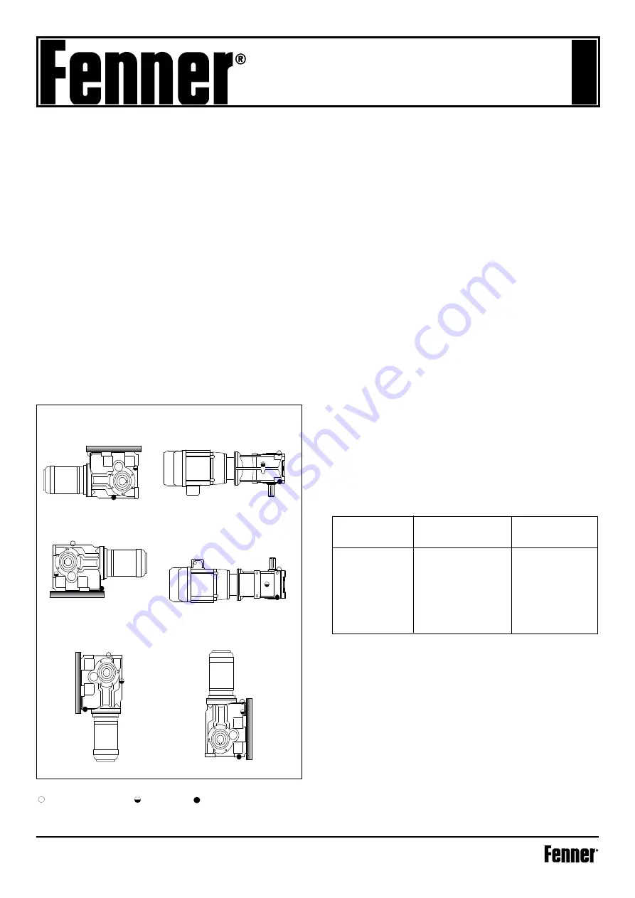
MOUNTING POSITIONS
Plug positions apply for sizes 893 and larger.
Ventilator/Filling Position Level Position Drain Position
SHAFT MOUNTING
Ensure that the shaft on to which the gear unit is to be mounted
and the gear unit bore are clean and free from burrs.
Liberally smear the shaft and bore with lubricants to aid
assembly and prevent fretting corrosion. Slide the unit on to the
driven shaft. Fit side fitting key.
DO NOT USE TAPER OR TOP
FITTING KEY
.
FOOT OR FLANGE MOUNTING
The Fenner series K is designed primarily as a shaft mounted
gearbox, however if a customer wishes to use the unit in the foot
mounted position all sizes have pre-cast feet built in to the gearcase
for mounting in the B3 position. Series K can also be used as a
flange mounted unit, standard output flanges area available as acces-
sories. Consult you local Authorised Distributor for details. Use the
tightening torques listed below for holding down bolts.
Clean shaft extensions and ventilator where fitted
The shafts of the unit and driven equipment should be in as perfect
alignment as possible. Fenaflex
®
couplings should be used when
shaft alignment cannot be assured and also when protection from
peak and vibrating torques are desirable. Ensure the base foundation/
flange mounting surface is flat*, vibration and torsionally rigid.
The drive should be mounted on a rigid support and bolted down
firmly using set screws to ISO grade 8.8 minimum. Ensure that ma-
chined mounting points are supported over their full area. If packing
is to be used, place either side of the mounting bolt. During the final
bolting down ensure the unit and/or baseplate are not distorted to
maximise unit performance.
For units mounted on bedplates, dowel two diagonally opposite feet
in to position.
Fit all guards required to comply with the factory acts, check the mo-
tor wiring for correct direction of rotation and check oil levels.
*Maximum permissible flatness error for mounting surface is 0.12mm.
MOTOR CONNECTIONS TO MAINS
Connection of the electric motor to the mains supply should be
made by a qualified person.The current rating of the motor will be
identified on the motor plate and correct sizing of the cables to
electrical regulations is essential.
STARTING UP
Prior to starting up the following procedure should be followed
1. Ensure Ventilator is fitted ( size 893 and above
2. Check Oil level (893 and above) top up if necessary
3. Ensure all safety devices are in place (i.e. guards fitted)
4. Remove any safety devices fitted to prevent machine rotation
Starting up should be performed or supervised by suitably quali-
fied personnel.
BREATHERS/MOUNTING POSITIONS
Sizes 890,891 & 892 are supplied for operation without breathers.
Size 893 is supplied for operation with a breather but to prevent
leakage during transit this unit is fitted with blanking plugs. It
is essential that when the unit is in its operating position the
relevant blanking plug is removed and replaced by the breather
plug (supplied) in the position indicated on the installation leaflet.
Sizes 894 to 898 are supplied for operation with a breather but are
despatched without oil.
It is essential that when the unit is in its operating position the
relevant blanking plug is removed and replaced by the breather
plug (supplied) in the position indicated on the installation leaflet.
1. Ensure Ventilator is fitted (size 893 and above)
2. Check Oil level (893 and above) top up if necessary
3. Ensure all safety devices are in place (i.e. guards fitted)
4. Remove any safety devices fitted to prevent machine rotation
Starting up should be performed or supervised by suitably quali-
fied personnel.
Ceiling Mounted (B8)
Left Hand Wall Mounting (B6)
Vertical Mounting Shaft Up (V6) Flange Mounting Shaft Up (V3)
Vertical Mounting Shaft Down (V5) Shaft Down Flange Mounting (V1)
Right Hand Wall Mounting (B7)
Standard Floor Mounted (B3)
Set Screw
Foot & Output
Motors to
Size
Flange Bolts
Gearhead
Torque (Nm)
M6
10
10
M8
25
18
M10
50
37
M12
85
64
M16
200
150
M20
350
260
M24
610
-
M30
1220
-
M36
2150
-
Summary of Contents for K Series
Page 10: ......


