Effective: October 2018
06-237172-002
5
TROUBLESHOOTING
Before troubleshooting the system, check the following items:
•
Verify all mechanical and electrical connections are secure
and tight.
•
Verify all system wiring is correct.
•
Verify there is a proper system ground. The igniter, flame
sensor, and ignition module must share a common ground
with the burner.
Nuisance shutdowns are often caused by a
poor or erratic ground.
•
Perform the instructions in “Checkout” on page 4, as the
first step in any troubleshooting.
•
Verify that the system is powered and that the thermostat is
calling for heat.
•
Verify the green power LED is lit, indicating 24 VAC power
to the control.
•
If the control proceeds to an error code on the red
diagnostic LED, troubleshoot per the Fault Conditions table
below:
The LED will flash on for 1/4 second, then off for 1/4 second
during a fault condition. The pause between fault codes is 3
seconds.
FLAME CURRENT MEASUREMENT
Flame current is the current that passes through the flame from
sensor to ground. To measure flame current, connect a True
RMS or analog DC micro-ammeter to the FC+ and the FC-
terminals. The reading should be 1.0 micro-amps DC or higher.
If the meter reads negative or below “0” on the scale, the meter
leads are reversed. Re-connect leads with proper polarity.
Alternately, a Digital Voltmeter may be used to measure the DC
voltage between the FC+ and FC- terminals. Each micro-amp
of flame current produces 1.0 VDC, so a reading of 2.6 VDC
would equate to 2.6 micro-amps.
A good burner ground that matches the control ground is critical
for reliable flame sensing.
INTERNAL CONTROL FAILURE
If the control detects an error in its software or hardware, all out-
puts are turned off and the red LED displays a steady ON condi-
tion. If this condition persists after an attempt to restart then the
control must be replaced.
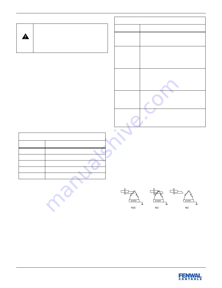
PROPER ELECTRODE LOCATION
Proper location of the electrode assembly is important for
optimal system performance. The electrode assembly should
be located so that the tips are inside the flame envelope and
about 1/2 inch (1.2 cm) above the base of the flame.
•
Ceramic insulators should not be in or close to the flame.
•
Electrode assemblies should not be adjusted or disassem-
bled. Electrodes should have a gap spacing of 0.125±
0.031 inch (3.12± 0.81 mm), unless otherwise specified by
the appliance manufacturer. If this spacing is not correct,
the assembly must be replaced. Electrodes are NOT field-
adjustable.
•
Exceeding the temperature limits can cause nuisance lock-
outs and premature electrode failure.
•
Electrodes must be placed where they are not exposed to
the appliance user in normal operation.
WARNING
Risk of Explosion or Fire
The 35-608 control cannot be serviced by the user.
If any control faults are detected, the 35-608 con-
trol must be replaced by qualified service person-
nel. Risk of explosion or fire can result if the control
module has been opened or with any attempts to
repair it, and the warranty is void.
Fault Conditions
LED Indication
Fault Mode
Off
Normal Operation
2 Flashes
Flame without call for heat
3 Flashes
Ignition Lockout
4 Flashes
Manual Reset Error
Steady On
Internal Control Failure
Troubleshooting Guide
Symptom
Probable Cause
1. Control does
not start, green
LED is off.
A. Mis-wired
B. 24 VAC Transformer bad
C. Fuse/Circuit breaker bad (no power)
2. Thermostat
on - no spark or
valve
A. Mis-wired
B. Bad thermostat, no voltage at thermostat
terminal TH
C. Bad control, check red LED for steady
on or flashing codes.
3. Valve on - no
spark during
TFI
A. Shorted electrode
B. Spark gap not correct. Set to .094-.156
inch.
C. High voltage cable is faulty or has a poor
connection.
4. Spark on -
valve off
A. Gas Valve coil open
B. Valve wire disconnected
C. Bad control, check voltage between gas
valve terminal MV and GND.
5. Flame okay
during TFI - no
flame sense
after TFI
A. Check electrode position and cleanliness
B. Check high voltage wire
C. Poor ground at burner
D. Poor flame, check flame current


