FALCON II
7
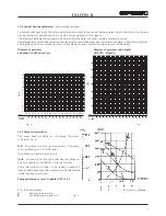
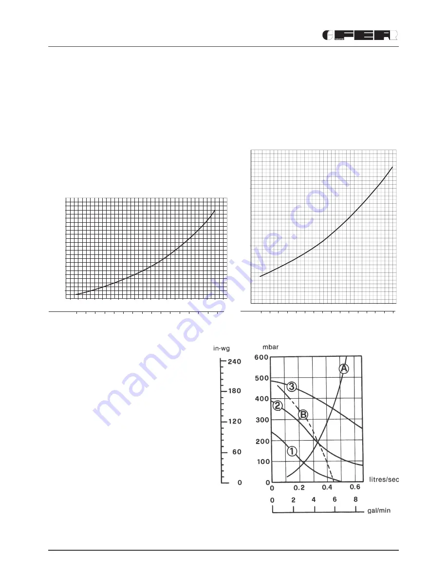
2.05 Pump characteristics
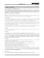
The pump head available for circulating the water
is given in fig. 6.
N.B.
- The pump is factory set at position 3. The pump
is a Grundfos type 15-50 UPS series.
Grundfos Pump performance graph
Note
- Minimum flow through boiler heat exchanger at
any time should not fall below 6 litres per minute.
If the total volume of water in the system exceeds 40
litres an additional expansion vessel must be fitted to the
central heating return pipe.
Pump performance curve Grundfos UPS 15-50
Fig. 6
1 2 3
Speed settings
A
Boilers pressure drop
B
Available pump head C.H.
2.04 Central heating adjustment
(not normally required)
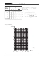
To adjust boiler heat input (thus also regulating heat output to the central heating water) simply adjust the main burner
via the electronic control board (fig. 4 and 5 and see paragraph 5.04 page 23).
The diagrams indicate the variation in heat output to the water as burner working pressure is varied.
Adjusting boiler output to the actual requirements of the central heating system will minimise boiler cycling thus saving fuel,
varying the output has virtually no effect on the efficiency and combustion characteristics of the boiler.
Diagram of pressures
and outputs with Natural gas
Fig. 4
Fig. 5
Diagram of pressures and outputs
with LPG (Propane)
2
3
4
5
6
7
8
9
10
11
12
13
12 13 14 15 16 17 18 19 20 21 22 23 24
11 12 13 14 15 16 17 18 19 20 21
kW
kcal/h
x 1000
mbar
14
25 26 27 28 29 30 31
22 23 24 25 26
kW
kcal/h
X 1000
m
bar
18 19 20 21 22 23
5
10
15
20
25
30
35
12 13 14 15 16 17
11 12 13 14
18 19 20
15 16 17
25 26 27 28 29 30
24
21
25 26
22 23 24
Summary of Contents for FALCON II
Page 43: ......


